8
Call Switches and Speakers
Flush-mounted switches require single-gang outlet boxes. Install outlet
boxes about four feet from the finished floor, in a location which will allow
personnel easy access to the switch for call-in and/or communicating via
the room speaker. Wall-mounted speakers should be installed at a
recommended height of 7-1/2 feet above the finished floor.
Grounds
– Do not connect cable shields to earth grounds or convenient
metal objects. It is important to connect cable shields only as shown in the
wiring diagrams.
Voice Call-In Option
Figure 8 shows room connections and the customer-supplied switch
required for voice call-in. The wiring must be completed by connecting the
shielded pair from the switch to the terminal strip at the rear of the MCP35A
chassis. The polarity of the inner conductors is not critical, but make cer-
tain to connect this cable shield to the shield already connected to the ter-
minal strip.
Note: Only one cable goes to the terminal strip. Usually, cables from all
room switches utilizing this function are connected by a common control
cable and one cable is run to the control panel. If this type of installation
is not practical, the control cables for two or more switches are run to the
control center and are connected in parallel at a junction box; a single
control cable is then run to the terminal strip at the rear of the MCP35A
chassis.
Call/Privacy Option
Figure 10 shows the room connections and the switch required for incor-
porating the optional privacy feature in the system.
Caution
:
To avoid electric shock, be sure to disconnect AC Power Cord
before removing the cover of the amplifier unit.
Warning
:
DO NOT perform any function requiring the removal of the
cover of the unit unless you are qualified to do so.
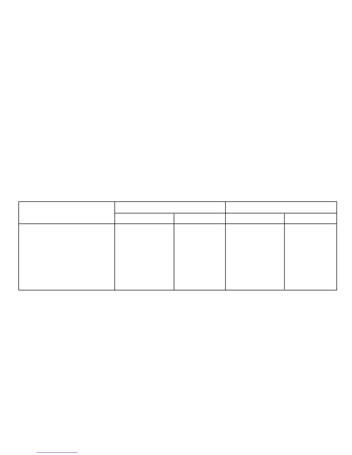
Type of Call Switch or
Device used with Speaker
Voice Call-In, Non-Private
(Customer-supplied DPDT Switch) 2* 0 1 8
None (Loudspeaker) 1 0 0 9
Call Switch (CA10A) 1 1 1 10A
Call Switch (CA11A) 1 1 1 10B
Wires from Room to Control Panel Wires from Room Switch to Room Speaker
No. 22 AWG Shielded No. 22 AWG No. 22 AWG Refer to Fig.
Table 1 – Cable Running Chart
* Alternative Method: Run two cables from room nearest the control panel and one cable from each remaining room.
Run one cable in a loop or branch circuit connecting all room switches.