Gain Adjustments
(Rear Panel)
Screwdriver-adjustable INPUT GAIN controls are accessible via the rear
panel for MIC 1, MIC 2, AUX, Tel Page, Talk, and Listen. Set the controls
so that signal clipping cannot occur.
Proceed as follows:
1. Apply input(s) to the desired channel(s).
2. Set the corresponding front panel control(s) to maximum.
3. Adjust the appropriate Input Gain control (looking at the rear panel, turn
clockwise to increase or counterclockwise to decrease gain) so that the
red O (overload) LED lights; then turn counterclockwise only until the
LED is extinguished.
Note: Talk and Listen controls should be set for adequate intercom level
(not indicated by an LED).
External MIC for MIC 1/Console MIC
(Rear Panel)
1. Locate and loosen the two screws securing the jumper link on the rear
chassis terminal strip connecting MIC 1 HI terminal to the CONS MIC
terminal.
2. Move the link away from the CONS MIC terminal.
3. Connect a balanced or unbalanced low-impedance microphone to the
MIC 1 terminals. Connect the cable shield to the GND terminal.
4.
Move the shunt on J4 to the OFF position to disable the monitor speaker
muting feature when the MIC 1 push button is selected
(see Fig. 2)
.
Note: J1 should be in the OFF position when the console mic is connected
to the MIC 1 input
(see Fig. 2)
.
Time Tone
(Rear Panel)
A tone signal sounds through all speakers when the time clock terminal is
grounded through a closure. (The tone may be used as a class change sig-
nal or for other purposes, such as a telephone night ringer or alarm signal.)
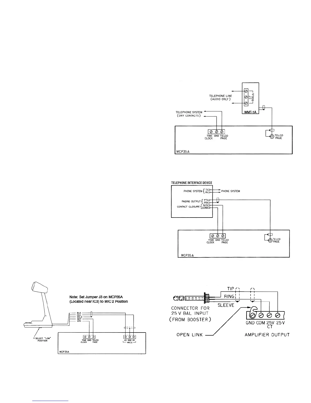
External Booster Amplifier
(Rear Panel)
Model BPA60 provides increased power output. To install, connect a cable
terminated in a male phone plug from the MCP35A Line Out jack to the
Hi-Z input jack on the rear panel of the amplifier. Connect the 25V output
from the amplifier to input jack labeled 25V BAL INPUT. Refer to Fig. 6.
Remote Emergency Telephone Paging
(Rear Panel)
Figures 3 and 4 show the connection of a telephone to the TELCO page
feature of the MCP35A.
Remote Emergency Microphone Paging
(Rear Panel)
The MIC 2 input may optionally be used in place of the Telco Page input
for use with a remote microphone (internal jumper). Figure 5 shows the
connection of the MBS1000A to the MIC 2 terminals. Refer to TELCO
PAGE/MIC 2 above for the proper configuration when the MIC 2 input
terminals are used for telephone page applications.
5
Figure 3 – Remote Emergency Page from
Telephone System Page Port
Figure 5 – Remote Emergency Microphone
Page with MBS1000A
Figure 6 – Booster Amplifier Output
Connection for MCP35A
Figure 4 – Remote Emergency Page using
Telephone Interface Device
Caution: Do not insert or remove this connector while power is on;
amplifier failure may result.