6
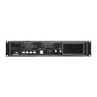
SBA225 Room Selector Panel
Bogen Model SBA225 Room Selector Panels are capable of connecting
up to 25 speaker-equipped locations to a PROGRAM, INTERCOM
channel, or off. Each unit provides 25 lever-action, three-position,
four-pole selector switches with positive detents, and red LED indicators.
Switch positions are graphically identified as PROGRAM A, OFF O, and
INTERCOM C, each with color-coded guidelines.
Each switch functions as follows:
PROGRAM / A – (Up position, amber color-code) Connects the speaker
station to the Program channel for distribution of program from microphone
or other program source. Overridden by Emergency Page, Telco Page,
and Time Signaling.
OFF / O – (Center position, white color-code) Disconnects the speaker
station from the system; overridden by Emergency Page, Telco Page,
All Rooms, and Time Signaling.
INTERCOM / C – (Down position, green color-code) Connects the
speaker station to the intercom channel. Overridden by Emergency Page,
Telco Page, and Time Signaling.
Note: To preserve intelligibility, only one station at a time should be
connected to the intercom channel.
A white tabular strip, protected by a clear plastic snap-off cover, is
provided for labeling the station controlled by each selector switch. When
stations are identified by numbers, it is common practice to connect and
label the switches from left to right (viewed from the operatorʼs position),
starting at the uppermost panel.
When a station makes a call to the control panel, the corresponding LED
lights on the SBA panel and a repetitive tone alerts the operator to the call.
The LED remains on until the call is acknowledged by placing the appro-
priate switch to the C position.
Each room selector panel has provisions for accommodating the add-on
Bogen Model SCR25A Call-In Module, providing the circuits necessary
when using the call-origination switches which do not contain silicon-
controlled rectifiers.
SBA225 Wiring
Across the rear of each switch bank is a row of male centerline terminals.
Each individual selector switch corresponds to the four terminals directly
behind it.
Note: The first three pins on the left (looking from the rear) and the last
pin on the right provide special functions and should not be connected to
speakers. Connectors used to connect speaker or handset wiring to the
SBA panel are standard parts stocked by many electronic parts distribu-
tors. We use Panduit .156 centerline connectors; however, equivalent
connectors are available by AMP or MOLEX. Wires are attached to
connectors using Panduit tool MRT-156F, or MCT with CTD-156F nose,
or equivalent.
Wire switch banks, as shown in Figure 12, using one female centerline
plug to terminate wires from the speaker and/or call switch. Connect the
shield to the ground terminal. This is the only place where speaker
cable shields should be grounded.
SCR25A Call-In Module
Caution: The installation of accessory equipment requires the removal of
protective covers; exposure of internal components presents an electrical
shock hazard. Accessory equipment should be installed by qualified
service personnel only
.
The Model SCR25A Call-In Module is an annunciator latching control bank
designed for use with Bogen SBA-Series Room Selector panels. The
SCR25A provides 25 silicon-controlled rectifiers and programmable
jumpers, and permits the use of either a momentary switch (such as the
Bogen Model CA17) or a telephone handset with fixed closure for call-in
from each staff location.
The SCR25A provides annunciator latching (as needed) to keep the
appropriate LED lamp illuminated until the call is acknowledged. Jumpers
are provided to select the method of call-in (momentary switch or fixed
closure handset).
The module is connected to the switch bank by a plug-in method and is
constructed of G-10 glass epoxy. Power supply is selectable by a jumper
and is taken from the switch bank or from an external power source.
Termination is via centerline connectors (Panduit or equivalent).
SCR25A Installation
Connections
1. Align the SCR25A module with the connector pins at the rear of the
SBA-Series panel and carefully press into place.
2. Make speaker and annunciator connections directly to the SCR25A
module as you would to the room selector panel.
Note:
The pins that normally would not have been used on the SBA-
series panel do not appear on the SCR25A panel.
Power Requirements
1. Jumper J26 in the upper right-hand corner of the SCR25A printed
circuit board must be in the Multi-Graphic position, as illustrated in the
diagram on the PC board.
2. Connect a wire from one of the pins marked P12, in the lower right-hand
corner, to the positive (+) terminal on an external 12V DC power supply.
Connect the negative (-) terminal on the power supply to ground on the
MCP35A. If more than one SCR25A is used, parallel P12 to each
SCR25A.
Note:
If only one or two SCR25A modules are used, they can be powered
from the +12V terminal on the rear of the MCP35A.
Mode Selection
For each channel using momentary switch contacts (no SCR) for call-in,
set the corresponding jumper (J1-J25) to the TOGGLE position (towards
the left, as looking at the rear).
For each channel to which a phone or SCR-equipped call-in switch (Bogen
CA10A or CA11A) is connected, set the corresponding jumper (J1-J25) to
the PHONE position (towards the right, as looking at the rear).
For clarity, two diagrams showing the relative positions of jumpers J1-J25
and J26 are screened onto the PC board.
Associated Equipment

 Loading...