5
Table 1: Control Factory Default Settings
Models
Temperature
Set Points
Defrost
Start Times
Defrost Duration
(Maximum)
Drip
Time
Fan
Delay
Defrost Termination
Set Point
EZY
Default
M - Cooler Models
Air Defrost
38˚F 4 / day 40 min. – – 40˚F 3
M - Cooler Models
Electric Defrost
35˚F 4 / day 40 min. 2 min. 1 min. 65˚F 2
L - Freezer Models
Electric Defrost
-10˚F 4 / day 40 min. 2 min. 1 min. 65˚F 1
RIGGING
Rigging holes are provided on all models. Caution should
be exercised when moving these units. To prevent damage
to the unit housing during rigging, cables or chains used
must be held apart by spacer bars. The mounting platform
or base should be level and located so as to permit free
access of supply air. The unit weather hood may be
removed for the rigging process. The condensing unit cover
(wrapper) should be left in place.
ACCESS REQUIREMENTS
Provide adequate space at the compressor end of the unit
for servicing. Provide two (2) feet of space above unit for
service.
INSPECTION
1. Each shipment should be carefully checked against the
bill of lading.
2. The shipping receipt should not be signed until all items
listed on the bill of lading have been accounted for.
3. Check packaging for signs of damage.
4. Any shortage or damages should be immediately
reported to the delivering carrier.
5. Damaged material becomes the delivering carrier’s
responsibility, and should not be returned to the
manufacturer unless prior approval is given to do so.
6. When unpacking the system, care should be taken to
prevent damage.
7. Avoid removing the shipping base until the unit has been
moved to the final destination.
8. Complete warranty return card for each unit and mail to
Heatcraft Refrigeration Products.
MOUNTING
The system requires an opening in the ceiling to the
dimensions stated on page 3. Mounting rails are located
at both ends of the chassis. Mounting rails may be used to
attach unit to ceiling. Through-bolts should be insulated
or non-conductive to prevent sweating. The chassis is
weather stripped around the air grille and will seal to the
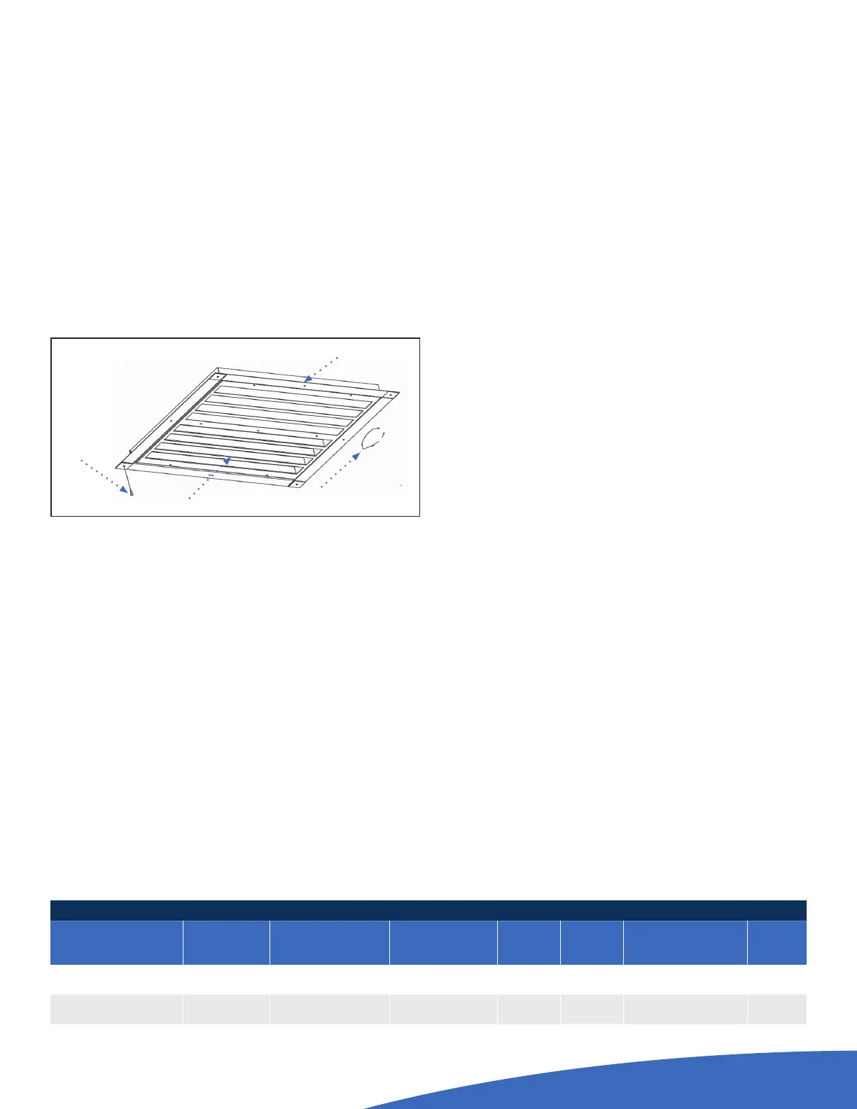
box roof. The trim ring (shipped loose), when provided,
should be installed around the air diuser when secured
with the hardware provided. Be sure to adhere to your local
standard construction codes.
GENERAL SAFETY INFORMATION
1. Installation and maintenance to be performed only by
licensed contractor.
2. Ensure that the structural integrity of the box can
withstand the weight of the PRO
3
(See Tech Bulletin for
unit weights).
3. Avoid contact with sharp edges and coil surfaces. They
are a potential injury hazard. Wear gloves during moving
and rigging.
4. Make sure all power sources are disconnected before
any service work is done on units.
CHANGING THE EZY
1.
Press Set button and hold in until the display flashes “PS”.
2. Press the Set Button and the display will change to “0”
and will begin to flash.
3. Press the up button until “22” is displayed.
4. Press the Set button.
5. Press the down button 2 times. “EZY” will be displayed.
6. Press the Set button.
7. Select the proper number for the model needed by
pressing the up or down key.
■ 1 - L Low temperature model
■ 2 - M Med temperature model - Electric Defrost
■ 3 - M Med temperature model - Air Defrost
8. Press Set and wait for unit to return out of
programming mode.
9. Disconnect power
10. Press the Set Button while turning unit On
11. “CE” should display to verify programming display
Self Drilling
Screw
Evaporator Grill
Ceiling of
Walk-In
Trim Pieces (4)
Overlap as shown
Trim Ring Installation Detail
 Loading...