
C
Christy HamiltonJul 31, 2025
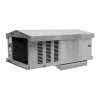
Why is the high temperature alarm showing on my Bohn PRO3 Fan?
- SStephen FranklinJul 31, 2025
The high temperature alarm might be showing on your Bohn Fan because the alarm delay after defrost is too short or the alarm threshold is too low.