Instruction Manual for F1300/1600 Mud Pump
17
shield ○8 is used for lifting dampener assembly. Before assembly thoroughly clean ring groove, gasket
ring ○1 and groove of mating flange and coat with grease.
Lifting the dampener to the corresponding position of mud pump discharge line, screw nut (R4) with
950~1265N.m (700~935ft.lbs) torque. Assure the connection part is flat and aligned by alternately
tightening the nuts.
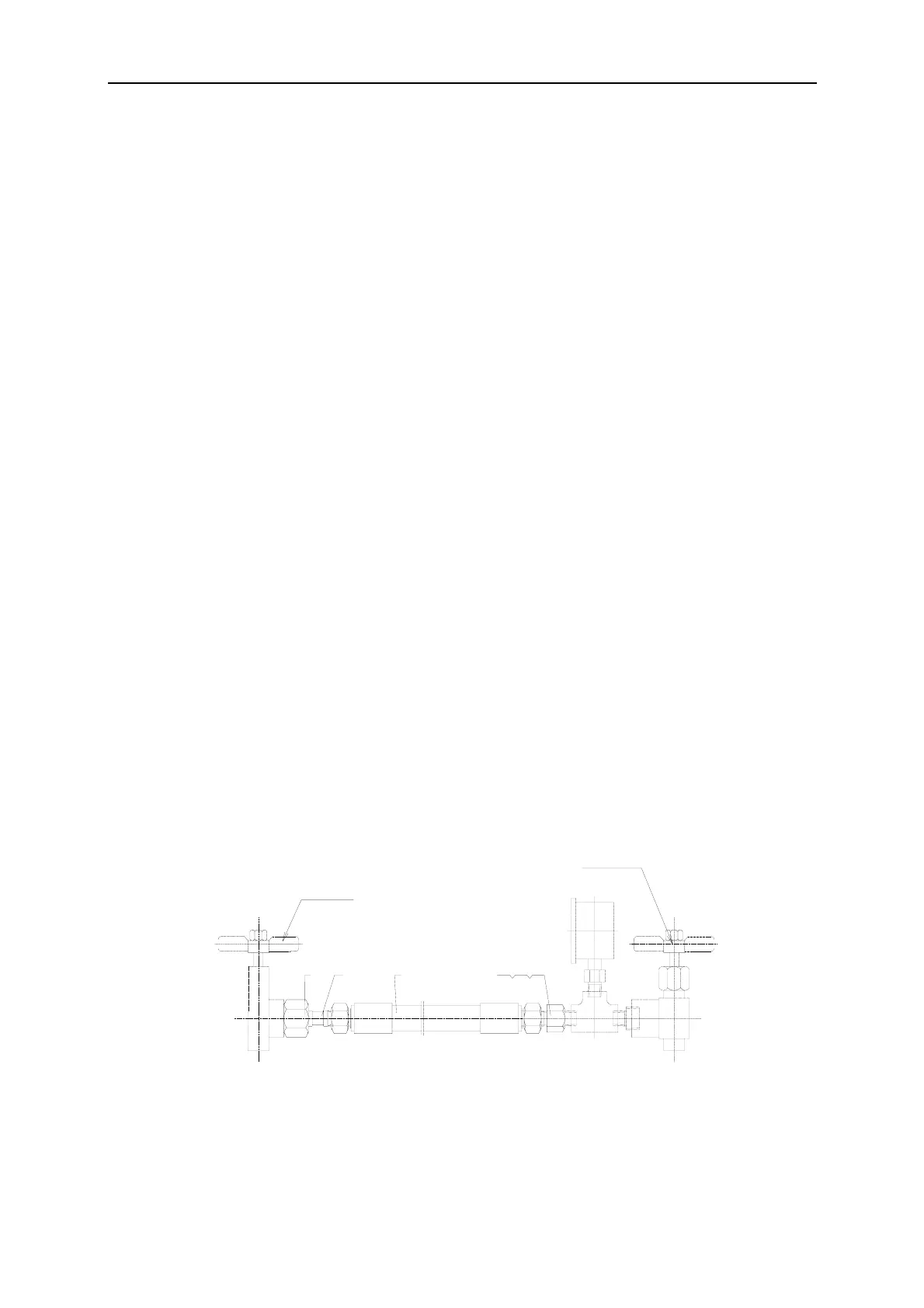
1.7.2 Air charging
A set of air charging device is attached when equipment leaves factory(air charging hose assembly of
dampener)please Operate as following procedure: (See Fig. 11)
a) Remove shield of pressure gauge of dampener, rotate valve cover of exhaust about 1/4-1/2 turn
to release the air pressure existed in pressure gauge area, then remove the exhaust valve.
b) Connect hose to the nitrogen cylinder valve and charge valve of dampener.
c) Open the charge valve of dampener.
d) Slowly open the nitrogen cylinder valve, use this valve to adjust incoming N
2
of dampener.
e) When the pressure gauge of dampener indicates pressure required then shut the nitrogen
cylinder valve.
f) Shut the charge valve of dampener.
g) Remove hose, cover the shield of pressure gauge, and then install the exhaust valve.
For getting best result, Precharge pressure should not be more than 2/3 of the pump discharge
pressure, or a maximum of 4.5 Mpa. (650psi)
Warning:
1. Only charge with compressed nitrogen or air. Do not charge with inflammable and
explosive gas such as oxygen and hydrogen etc.
2. When make maintenance to the dampener, insure both the dampener pressure gangue
and the pump pressure gangue indications is zero. Low pressure can’t be exactly shown
by the dampener pressure gangue, which may cause an accident.
Fig. 11
(1) Nut C5/8″ (2) Seal connector (3) C-type connector hose ⑷ Joint (5) Gasket (6)Pipe plug
氮气瓶开关
12
3
空气包充气阀
4
65