Do you have a question about the BONAIRE B009RS and is the answer not in the manual?
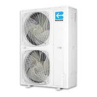
Describes the Bonaire Ducted Reverse Cycle air conditioner system comprising indoor and outdoor units interconnected by tubes and cable.
Emphasizes that installation must be by authorized technicians following specifications to avoid warranty invalidation.
Provides dimensions and weights for B007RS, B009RS, and B012RS outdoor units in a table format.
Details dimensions and weights for B015RS, B016RT, and B019RT outdoor units, continuing the table.
Outlines criteria for selecting outdoor unit location, focusing on access, disturbance, and necessary clearances.
Presents a table of dimensions and net weight for various indoor unit models (B007HD to B019HD).
Details mandatory and fan removal clearance options for indoor units, specifying required measurements.
Diagram labeling key indoor unit components and connection points for installation.
Guides on choosing the indoor unit location, considering airflow, noise, obstructions, and structural support.
Provides notes on return air ducting, clearances, and access to the electrical control box for indoor unit installation.
Details mounting the indoor unit on a platform or floor, including noise reduction with rubber pads.
Explains suspending the indoor unit using a hanging bracket kit and threaded rod, emphasizing secure fixing.
Instructs on adjusting unit level for proper drainage and securing suspension mounts, crucial for operation.
Illustrates the outdoor unit, labeling components like fans, control board, and connection points for installation.
Details installing the outdoor unit on a flat surface elevated for water drainage, listing required components.
Explains routing refrigerant tubes and electric cable through a wall, including drainage hose considerations.
Provides notes on sealing tubing, avoiding hot zones, minimizing bends, insulating lines, and cleaning tubes.
Presents a table with connecting line diameters, tubing lengths, and maximum height differences for various unit models.
Illustrates three tubing installation scenarios (outdoor above, same level, outdoor below) with oil trap requirements.
Details pipe installation, emphasizing flare preparation, cutting, de-burring, and flaring tool usage with depth specifications.
Outlines requirements for pipe welding preparation, including capping, clean copper piping, and proper cutting tools.
Explains the pipe welding process, including safety, brazing rod, heating, nitrogen flow, and connecting tube torque.
Instructs on connecting and tightening flare nuts, coating surfaces with oil, and leak checking with torque values.
Details evacuating the system using a vacuum pump, checking for leaks, and opening valves for operation.
Specifies adding refrigerant based on liquid line length and warns against exceeding maximum pipe lengths.
Provides instructions for drain line installation, including slope, traps, flexible hose connection, and leak verification.
States that electrical connections must be made by authorized electricians, following local codes, and that the system must be grounded.
Explains power provision, unit control cable, and thermostat communication options (RF, Low Voltage, conventional).
Details connecting the outdoor unit to mains power via a dedicated circuit breaker and control cable.
Provides a wiring diagram for single-phase indoor units, showing connections to the control board and power supply.
Presents the wiring diagram for single-phase outdoor units, detailing connections to the PCB, transformer, and components.
Illustrates the wiring diagram for 3-phase outdoor units, detailing connections for power supply, control board, and components.
Advises on pre-installation checks for the control system, including antenna/cable connection, batteries, and mains power.
Guides on mounting the thermostat approximately 1.5 meters above the floor, securing the cradle, and routing cables.
Details setting up the thermostat, including battery installation for RF units and coding the unit to the control board.
Explains the 4-minute window process for coding the unit, involving pressing specific buttons until 'CODE' flashes.
Guides on entering setup mode and modifying system functions (A-H) using FUNCT and SELECT buttons.
Provides a table explaining the operation and meaning of Red LED1 and Green LED2 indicators during setup and operation.
Describes how to enter commissioning mode, with results indicating safety functions are disabled for 45 minutes.
Explains how to initiate an indoor unit test sequence, checking fan speeds and zone relays.
Details initiating an outdoor unit test, checking compressor, reversing valve, and fan speeds.
Provides a checklist for site, indoor unit, outdoor unit, and communications to ensure proper installation and operation.
Instructs on explaining operating instructions, filter maintenance, unit operation, warranty, and providing the owner's manual.
| Brand | BONAIRE |
|---|---|
| Model | B009RS |
| Category | Air Conditioner |
| Language | English |