Do you have a question about the BONAIRE B012RS and is the answer not in the manual?
Overview of Bonaire Ducted Reverse Cycle air conditioners, their components, and control methods.
Crucial safety warning about professional installation and warranty validity.
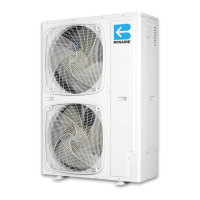
Dimensional data and specifications for Bonaire outdoor units B007RS, B009RS, B012RS.
Dimensional data and specifications for Bonaire outdoor units B015RS, B016RT, B019RT.
Key criteria for selecting the optimal location for outdoor unit installation.
Illustrations showing required clearances for outdoor unit installation from walls, top, and sides.
Detailed dimensions for various Bonaire indoor unit models.
Table detailing mandatory and optional clearances for indoor unit maintenance.
Diagram identifying key components and connection points of the indoor unit.
Guidelines for selecting the proper location for the indoor unit installation.
Important notes regarding ducting, access for servicing, and clearances for indoor unit installation.
Methods for mounting and leveling the indoor unit.
Diagram showing external and internal components of the outdoor unit.
Guidance on installing the outdoor unit on various flat surfaces.
Instructions for routing refrigerant tubes and drainage hose between units.
Key guidelines for handling and installing refrigerant tubing for optimal performance.
Table detailing tubing diameters, lengths, and height differences for various models.
Schematics illustrating three recommended scenarios for refrigerant tubing installation.
Detailed instructions for preparing tube ends for flaring connections.
Requirements and precautions for preparing copper piping for welding.
Guidance and safety precautions for pipe brazing and welding operations.
Steps for connecting flared tube ends and torque specifications.
Step-by-step guide for evacuating the system using a vacuum pump.
Instructions for valve operation and leak detection before system startup.
Guidance on adding refrigerant based on pipe length and unit specifications.
Steps for correctly installing the condensate drain line with traps and proper slope.
Details on power supply and control wiring for the indoor unit.
Explanation of different control system connection methods (RF/Low Voltage/Thermostat).
Instructions for connecting power and communication cables to the outdoor unit.
Detailed wiring diagram for single-phase indoor unit connections.
Wiring diagram for single-phase outdoor unit connections.
Wiring diagram for three-phase outdoor unit connections.
Checks before control installation and guidelines for thermostat placement.
Instructions for installing batteries, connecting, and coding the thermostat.
Explanation of LED indicators and their meanings during operation.
Procedure for entering setup mode and adjusting system operating parameters.
Steps for initiating installer commissioning or setup/service modes.
Procedures for performing indoor and outdoor unit service tests.
Detailed interpretation of LED effects and their corresponding actions.
Checklist for ensuring proper installation, operation, and communication.
Critical note regarding RF interference and its causes.
Steps for explaining operation, features, and warranty to the customer.
| Brand | BONAIRE |
|---|---|
| Model | B012RS |
| Category | Air Conditioner |
| Language | English |