30
Helical in-line gear units C 11, C 21, C 31
(S4)
Values in the table are given in mm.
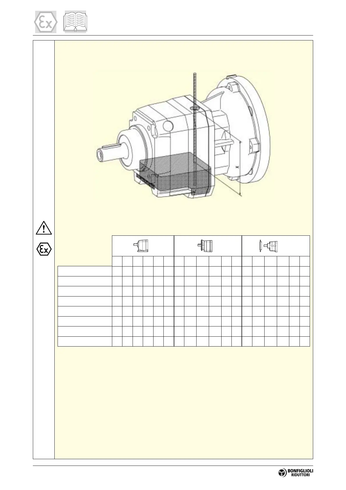
To check the oil level, proceed as follows:
1. Place the gear unit in the mounting position as shown in diagram (S4).
2. Insert a dipstick through the yellow service cap (on top of the gear unit) until it touches the
floor of the casing. Mark the level of the upper surface of the casing on the dipstick in this po
-
sition.
3. Extract the dipstick and measure the distance X shown in diagram (S4) above.
4. The value X must be less than the value given in table (A7).
B3 B6 B7 B8 V5 V6 B5 B51 B53 B52 V1 V3 B5 B51 B53 B52 V1 V3
C 11 2_ P63-P71 70 70 70 70 70 45 70 70 70 70 60 30 70 70 70 70 60 30
C 11 2_ P80…P112 75 75 75 75 75 45 75 75 75 75 70 30 75 75 75 75 70 30
C 21 2_ P63-P71, HS 70 70 70 70 70 40 70 70 70 70 70 45 70 70 70 70 70 45
C 21 2_ P80…P112 75 75 75 75 75 40 75 75 75 75 75 45 75 75 75 75 75 45
C 21 3_ P63-P71 50 50 50 50 50 30 50 50 50 50 50 30 50 50 50 50 50 30
C 21 3_ P80…P112 55 55 55 55 55 30 55 55 55 55 55 30 55 55 55 55 55 30
C 31 2_ P63…P112, HS 65 65 65 65 60 60 65 65 65 65 55 55 65 65 65 65 55 55
C 31 3_ P63…P112 55 55 55 55 55 55 55 55 55 55 55 55 55 55 55 55 55 55
(A7)
P
F
U-UF
 Loading...