25 / 64
IOM Manual VF-W_ATEXgb - Translation of original instructions in Italian - Rev 03_0 - 30/09/16
2. Loosen the pair of nylon wheels in relation to the micro switch which corresponds to the direction of
rotation previously observed (carrying the letter A in the example alongside). Use the 1.5 mm Allen key
supplied with the device.
Set the two grooves side by side and rotate both wheels manually until the roller of the switch snaps into
the grooves and a click can be heard. Then lock both the wheels in that position by screwing down the
respective grub screws.
To set the other end position, drive the gearmotor in the opposite direction until that end position is
reached. Follow same procedure described above, operating on the correspondent micro-switch. At the
end, close the lid and lock it with the 4 nos. socket head screws.
N.B. With reference to the revolutions of the output shaft, the limit switch range is 0 – 43 turns.
5.6 CALIBRATING THE TORQUE LIMITER SLIPPING TORQUE
A preliminary slip torque setting is conducted at the factory. Reference is made to torque rating Mn
2
[n
1
=1400] of the captioned VF or W gear unit.
Here below the operations performer at the factory for the initial adjustment are listed. Same steps, with the
exception of step (2), must be followed when a different torque setting is required.
1. Ring nut is tightened until spring washers are sufciently loaded that manual rotation is hardly possible.
2. By means of an engraver marks are made, in identical (angular) position, on both the ring nut and the
hollow shaft. Setting will then be referred to as the zero-point for the consequent slip torque adjustment,
through turning of the ring nut.
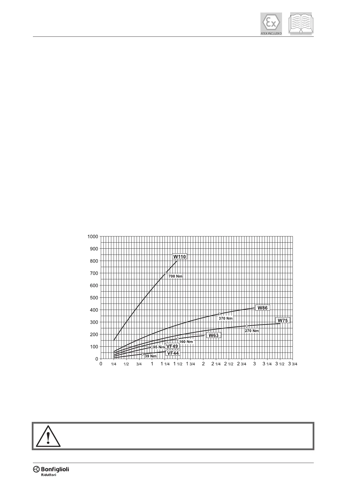
3. Ring nut is then turned of the number of turns, or fraction of, corresponding to nominal torque rating
Mn
2
of the captioned gear unit. In this case the diagram shown here under refers as to the proportion
between number of turns and transmissible torque. Same diagram comes handy for customised torque
adjustments, should these be required with time.
N. of ring nut turns
Torque [Nm]
5.7 INSTALLING CONNECTING ELEMENTS
Use the utmost caution when installing the various components, to ensure that no damage is caused to the
gearbox and its parts, such as oil seals and mating surfaces, or internal parts such as gears and bearings.
Make sure that you have access to suitable lifting equipment to perform the installation operations
correctly.
 Loading...