230
FEEDER CABLE SECTION
Type “H05RR-F”
230 V ac 3 x 2,5 mm
2
(*)
400 V 2N ac
5 x 1,5 mm
2
(*)
400 V 2N ac
4 x 1,5 mm
2
(*)
(*) –
Connection with wall box connection
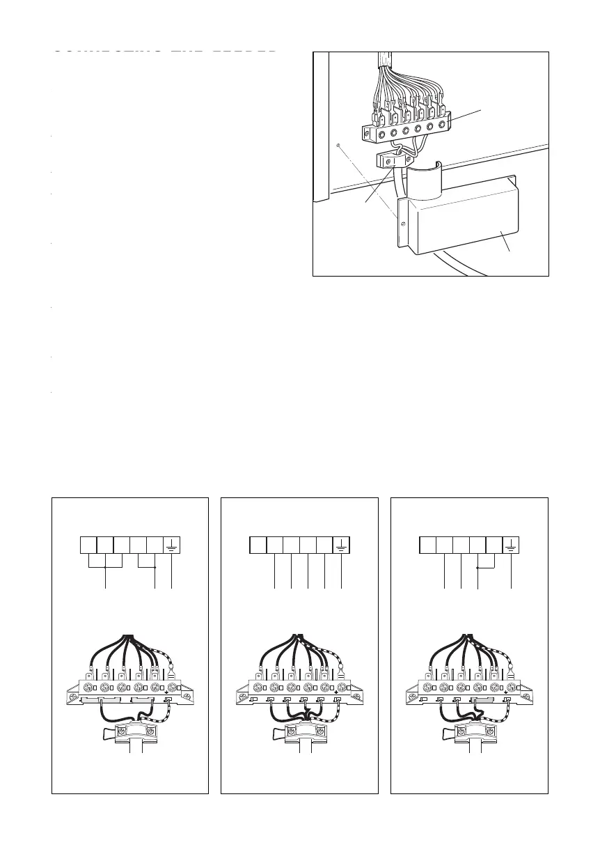
CONNECTING THE FEEDER
CABLE
To connect the feeder cable to the cook-
er it is necessary to:
– Remove the two screws that hold
shield A behind the cooker.
– Open completely the cable clamp D.
– Position the U bolts onto terminal block
B (fig. 10.1) according to the diagram
in fig. 10.2a, 10.2b, 10.2c.
– Insert the feeder cable into the cable
clamp D. The supply cable must be
of a suitable size (see the section
“Feeder cable section”).
– Connect the phase and earth cables
to terminal B according figures 10.2a,
10.2b, 10.2c.
– Pull the feeder cable and block it with
the cable clamp D.
– Re-mount shield A.
N.B. The earth conductor must be left
about 3 cm longer than the others.
CONNECTING THE FEEDER CABLE
WARNING: If the power supply cable is
damaged, it must be replaced only by
an authorised service agent in order to
avoid a hazard.
To connect the feeder cable to the cooker
it is necessary to:
• Remove the two screws that hold
shield “A” behind the cooker.
• Open completely the cable clamp “D”.
• Position the U bolts onto terminal
block “B”
(fig. 10.1) according to the
diagram in figs. 10.2a, 10.2b, 10.2c.
• Insert the feeder cable into the cable
clamp “D”. The supply cable must
be of a suitable size (see the section
“Feeder cable section”).
• Connect the phase and earth cables
to terminal “B” according figures
10.2a, 10.2b, 10.2c.
• Pull the feeder cable and block it with
the cable clamp “D”.
• Re-mount shield “A”.
N.B. The earth conductor must be left
about 3 cm longer than the others.
1
5
4
3
2
L
1
PE
400 V 2N~
L
2
N
2 3 4 51
PE
L1
L2
N
2 3 4 51
N(L2)
PE
L1
1
5
4
3
2
L
1
N
(L
2
)
PE
230 V~
1
5
4
3
2
L
1
N
2
PE
400 V 2N~
L
2
N
1
2 3 4 51
PE
L1
L2
N2N1
Fig. 10.2a
Fig. 10.2b
Fig. 10.2c
A
D
B
Fig. 10.1
230 V ac
400 V 2N ac 400 V 2N ac


 To Next Page