9 708 069 951 Page8
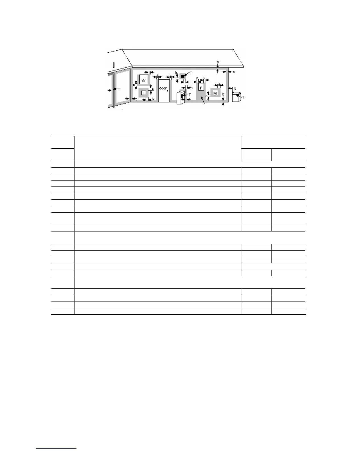
Clearance of flue terminals
T = Flue Terminal M = Gas Meter Shaded area indicates
prohibited area
I = Mechanical air inlet P = Electrical meter or fuse box W = Window
Ref Item Minimum Clearance
mm
Natural
draft
Fan
assisted
a Below eaves, balconies and other projections
Appliances up to 50MJ/h input 300 200
Appliances over 50 MJ/h input 500 300
b From the ground, above a balcony or other surface 300 300
c From a return wall or external corner 500 300
d From a gas meter 1000 1000
e From an electricity meter or fuse box (P) 500 500
f From a drain pipe or soil pipe 150 75
g Horizontally from any building structure or obstruction facing a flue
terminal
500 500
h From any other flue terminal, cowl, or combustion air intake 500 300
j Horizontally from an opening window, door, non-mechanical air inlet. Or other opening
into a building with the exception of sub floor ventilation
Appliances up to 150 MJ/h 500 300
Appliances over 150MJ/h input up to 200 MJ/h input 1500 500
Appliances over 200 MJ/h input 1500 1500
All fan assisted flue appliances in the direction of discharge 1500
k From a mechanical air inlet, including spa blower 1500 1000
n Vertically below an openable window, non-mechanical air inlet, or any other opening into a
building with the exception of sub-floor ventilation:
Space heaters up to 50 MJ/h 150 150
Other appliances up to 50 MJ/h 500 500
Appliances over 50 MJ/h and up to 150 MJ/h input 1000 1000
Appliances over 150 MJ/h input 1500 1500
Extract from AG601 For use as a guide only. Refer to AS5601/AG601 for
clearance
25/10/2011