Do you have a question about the Bosch 6806 and is the answer not in the manual?
Details warranty coverage and technical specifications for the dishwasher.
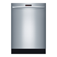
Explains where to find the model and serial number tags on the unit.
Describes the dishwasher's operational components and systems.
General notes pertaining to Section 1 topics.
Explains how to operate the SHU 3000 and 4000 series dishwashers.
Details cycle options, duration, and water usage for specific models.
Explains how to operate the SHI and SHU 4300 series dishwashers.
Details cycle options, duration, and water usage for specific models.
Explains how to operate the SHU 5300 series dishwashers.
Details cycle options, duration, and water usage for specific models.
Explains how to operate the SHI and SHU 6800 series dishwashers.
Details cycle options, duration, and water usage for specific models.
General notes pertaining to Section 2 topics.
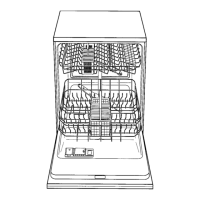
Describes the dishwasher racks and how to adjust or remove them.
Details the internal components of the dishwasher.
Explains the operation and filling of the detergent and rinse agent dispensers.
Discusses factors affecting washability and the dishwasher's drying system.
General notes pertaining to Section 3 topics.
Provides instructions for removing the outer door panel of the dishwasher.
Identifies and lists components visible after removing the outer door.
Explains how the PTC actuator and reed switch operate the dispenser.
Details the steps to remove the entire dispenser assembly.
Describes the removal and separation of the facia assembly.
General notes pertaining to Section 4 topics.
Details the electrical connection and wiring for the dishwasher.
Explains the replacement of the circulation motor capacitor.
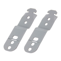
Describes how to adjust the leveling legs for stability.
Details the removal and replacement of the water inlet valve.
Instructions for removing the drain motor from the dishwasher.
General notes pertaining to Section 5 topics.
Describes how to access internal components from the left side panel.
Lists and identifies components accessible from the left side.
Explains the operation of the water inlet and discharge systems.
Details the steps for removing water inlet and discharge system components.
Describes how to access internal components from the right side panel.
Lists and identifies components accessible from the right side.
Explains the function and operation of the NTC sensor.
Provides detailed steps for removing the NTC sensor.
General notes pertaining to Section 7 topics.
Details the procedure for removing the dishwasher tank.
Lists components accessible after tank removal.
Step-by-step instructions for removing the circulation pump and motor.
Explains how to assemble and replace the circulation pump and motor.
Provides instructions for removing the heater assembly.
Details the components and installation of the heater assembly.
Explains the function and potential replacement of the aqua sensor.
Details how to remove and replace the door springs.
General notes pertaining to Section 8 topics.
Details test programs and identifies fault codes for the dishwasher.
Provides a detailed electrical schematic of the dishwasher's components.
Illustrates the wiring connections between various dishwasher components.
Shows the sequence of operations and timer positions for different cycles.
Presents a detailed electrical schematic of the dishwasher's system.
Illustrates the wiring connections for the dishwasher's electrical system.
Depicts the sequence of operations and timer positions for various cycles.
Shows the schematic and connections for the dishwasher's control unit.
Illustrates the wiring connections of the dishwasher's main components.
Details the wiring connections for the dishwasher's electrical system.
Shows the wiring connections for various dishwasher components.
Provides a schematic view of the dishwasher's electrical system.
Illustrates the wiring connections for specific dishwasher models.
| Type | Freestanding |
|---|---|
| Control Type | Electronic |
| Delay start | Yes |
| Child lock | Yes |
| Number of Place Settings | 13 |
| Water consumption | 9.5 l |
| Programs | 6 |
| Dimensions (H x W x D) | 60 cm x 60 cm x 60 cm |