English – 2
Product description and
specifications
Intended use
The Bosch drive unit of the system generation the smart
system is intended exclusively for driving your eBike and
must not be used for any other purpose.
In addition to the functions shown here, changes to software
relating to troubleshooting and functional modifications may
be introduced at any time.
Product features
Individual illustrations in these operating instructions may
differ slightly from the actual conditions depending on the
equipment of your eBike.
The numbering of the components shown refers to the illus-
trations on the graphics pages at the beginning of the
manual.
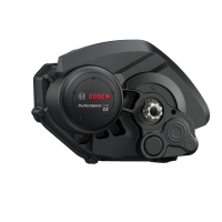
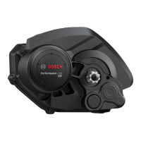
(1)
Drive unit
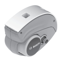
(2)
Speed sensor
a)
(3)
Spoke magnet
(4)
CenterLock magnet
b)
(5)
Rim magnet
a) different sensor type and installation position is possible
b) different installation position is possible
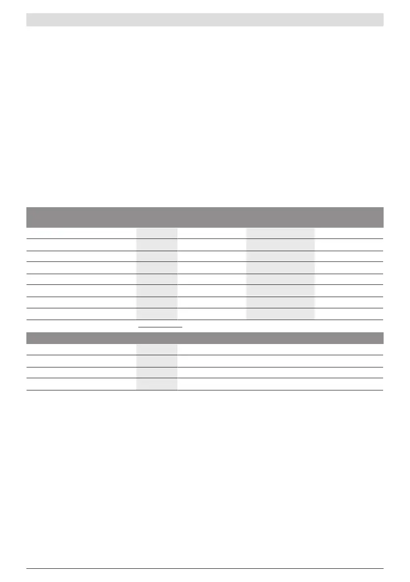
Technical data
Drive unit DriveUnit
Active Line
DriveUnit
Active Line Plus
DriveUnit
Performance Line
Product code BDU3320 BDU3340 BDU3360
Continuous rated power W 250 250 250
Torque at drive, max. Nm 40 50 75
Rated voltage V= 36 36 36
Operating temperature °C –5to+40 –5to+40 –5to+40
Storage temperature °C +10to+40 +10to+40 +10to+40
Protection rating IP55 IP55 IP55
Weight, approx. kg 2.9 3.2 3.2
The Bosch eBike systems use FreeRTOS (seewww.freertos.org).
Bicycle lights
A)
Voltage approx. V= 12
Maximum power
– Front light W 17.4
– Tail light W 0.6
A) Depends on legal regulations, not possible in all country-specific models via the eBike battery
Inserting a bulb incorrectly can cause it to blow.
Information on the noise emissions of the drive
unit
Typically, the A-weighted noise emission level of the drive
unit is<70dB(A). A key feature of the<eBike Alarm> ser-
vice is that the drive unit will emit an alarm tone in response
to unauthorised movement of the eBike. This alarm tone can
exceed a noise emission level of 70dB(A) and measures
80dB(A) at a 2m distance from the drive unit. The alarm
tone is only available once the<eBike Alarm> service has
been activated and can be deactivated via the appeBike
Flow.
Assembly
Checking the speed sensor (see figure A)
Speedsensor (slim)
The speed sensor(2) and its CenterLock magnet(4) or
spoke magnet(3) are mounted ex works in such a manner
that the magnet, after a turn of the wheel, moves past the
speed sensor with a clearance of at least 2mm, yet no more
than 15mm.
If any structural changes are made, the correct distance
between the magnet and the sensor must be complied with
(see figureA).
Note: Make sure you do not damage the sensor or the sensor
holder when fitting or removing the rear wheel.
0 275 007 3D2 | (13.02.2023) Bosch eBike Systems