48
|
Installation Instructions
Bosch 96% AFUE Condensing Gas Furnace - BTC 770503101 J (06.2023)
When using a single stage thermostat, second stage delay is based on the setting of
switch S1-1, S1-2 shown below.
Option Switches S1-1 & S1-2 Positions
Delay Time:
On "S1" set switch #
1 2
Off* Off Off
10 min On Off
Auto min Off On
20 min On On
Table 23 2nd Stage Delay For Single Stage Thermostats
* Factory default setting– two stage thermostat
2. Cooling Mode (if applicable)
In a typical single stage cooling system (Y connection), a call for cool is initiated by
closing the thermostat contacts. This energizes the compressor and the electronic
air cleaner (optional).
The circulator will be energized at cool speed after the COOL delay-to-fan-on
period. After the thermostat is satisfied, the compressor is de-energized and the
COOL delay-to-fan-off period begins. After the COOL delay-to-fan-off period ends,
the circulator and the electronic air cleaner are de-energized.
3. FAN Mode
If the thermostat fan mode is set to ON, the circulator fan (low heat speed) and
optional electronic air cleaner are energized. When the fan mode is returned to
AUTO, the circulator fan and electronic air cleaner (optional) are deenergized.
11.5 Gas Manifold Pressure Measurement and Adjustment
NOTICE:
f To prevent unreliable operation or equipment damage,
the gas manifold pressure must be as specified on the unit
rating plate. Only minor adjustments should be made by
adjusting the gas valve pressure regulator.
This valve is shipped from the factory with the regulator preset to 3.5 in. WC.
Consult the appliance rating plate to ensure burner manifold pressure is as
specified. If another outlet pressure is required, follow these steps (see Table 24
and Fig. 38):
1. Turn OFF all electrical power to the system.
2. Using a 3/32 inch hex wrench,,loosen outlet pressure tap screw one turn.
Do not remove screw.
3. Attach a hose and manometer to the outlet pressure barb fitting of valve to
overlap at least 3/8”
4. Turn ON system power and set thermostat to a call for heat.
5. Using a leak detection solution or non-chlorine soap suds, check for leaks at
hose connection. Bubbles forming indicate a leak. SHUT OFF GAS AND FIX
ALL LEAKS IMMEDIATELY!
6. Remove burner access panel.
7. Remove regulator screw cover. Turn regulator screw either clockwise to
increase pressure or counter clockwise to decrease. Always adjust regulator
to provide the correct pressure according to the original equipment
manufacturer specifications listed on the appliance rating plate.
8. Replace regulator screw cover and finger-tighten securely.
9. Turn OFF all electrical power to the system.
10. Remove manometer and hose from outlet pressure tap.
11. Tighten outlet pressure tap clockwise 7 in-Ibs minimum to seal port.
12. Replace burner access panel.
13. Turn ON system power and set thermostat to call for heat.
14. Using a leak detection solution or non-chlorine soap suds, check for leaks at
hose connection. Bubbles forming indicate a leak. SHUT OFF GAS AND FIX
ALL LEAKS IMMEDIATELY!
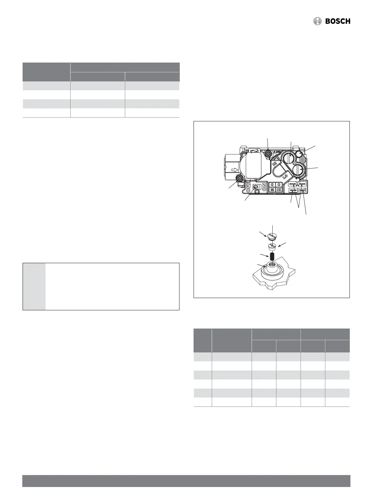
Figure 44
HIGH FIRE COIL TERMINAL (HI)
COMMON TERMINALS (C)
COAXIAL COIL
TERMINAL (M)
ON/OFF SWITCH
INLET PRESSURE
TAP
MANIFOLD PRESSURE
TAP
REGULATOR VENT
LOW FIRE
REGULATOR
ADJUSTMENT
HIGH FIRE
REGULATOR
ADJUSTMENT
Regulator
Cover
Screw
Regulator
Spring
Plastic
Regulator
Adjustment
Screw
Regulator
Sleeve
Gas valve and regulator adjustment
15. Measure gas manifold pressure with burners firing. Adjust manifold
pressure per the Manifold Gas Pressure table.
Input
Rating
KBTU/H
Furnace Model
Range Orifice Size
Natural
Gas
Propane
Gas
Natural
Gas
Propane
Gas
60 BGH96M060B3B 3.5" W.C 10" W.C 45 55
80 BGH96M080B3B 3.5" W.C 10" W.C 45 55
80 BGH96M080C4B 3.5" W.C 10" W.C 45 55
100 BGH96M100C5B 3.5" W.C 10" W.C 45 55
100 BGH96M100D5B 3.5" W.C 10" W.C 45 55
120 BGH96M100D5B 3.5" W.C 10" W.C 45 55
Table 24 Manifold Gas Pressure
The final manifold pressure must not vary more than,± 0.3 in. WC from specified
manifold pressure.
Any necessary major changes in gas flow rate should be made by changing the size
of the burner orifice.