| 49
Installation Instructions
Bosch 96% AFUE Condensing Gas Furnace - BTC 770503101 J (06.2023)
11.6 Gas Input Rate Measurement (Natural Gas Only)
The gas input rate to the furnace must never be greater than that specified on the
unit rating plate. To measure natural gas input using the gas meter, use the following
procedure.
1. Turn OFF the gas supply to all other gas-burning appliances except the
furnace.
2. While the furnace is operating, time and record one complete revolution of
the smallest gas meter dial.
3. Calculate the number of seconds per cubic foot (sec/ft³) of gas being
delivered to the furnace. If the dial is a one cubic foot dial,,divide the
number of seconds recorded in step 2 by one. If the dial is a two cubic foot
dial, divide the number of seconds recorded in step 2 by two.
4. Calculate the furnace input in BTUs per hour (BTU/hr). Input equals the
installation's gas heating value multiplied by a conversion factor (hours to
seconds) divided by the number of seconds per cubic foot. The measured
input must not be greater than the input indicated on the unit rating plate.
Example:
Installation's gas heating (HTG) value: 1,000 BTU/ft³ (Obtained from gas supplier)
Installation's seconds per cubic foot: 34 sec/ft³
Conversion Factor (hours to seconds): 3600 sec/hr
Input = (Htg. value x 3600) + seconds per cubic foot
Input = (1,000 BTU/ft3 x 3600 sec/hr) + 34 sec/ft³
Input = 106,000 BTU/hr
This measured input must not be greater than the input indicated on the unit rating
plate.
5. Turn ON gas and relight appliances turned off in step 1. Ensure all the
appliances are functioning properly and that all pilot burners are operating.
11.7 Temperature Rise Adjustment
Air temperature rise is the temperature difference between supply and return
air. The proper amount of temperature rise is usually obtained when the unit is
operated at the rated input with the "as shipped" blower speed. If the correct
amount of temperature rise is not obtained, it may be necessary to change the
blower speed.
NOTICE:
f An incorrect temperature rise can cause condensing in or
overheating of the heat exchanger. Determine and adjust
the temperature rise as follows. The temperature rise must
be within the range specified on the rating plate.
Temperature Rise Adjustment
1. Operate furnace with burners firing for approximately 15 minutes. Ensure
all registers are open and all duct dampers are in their final (fully or partially
open) position.
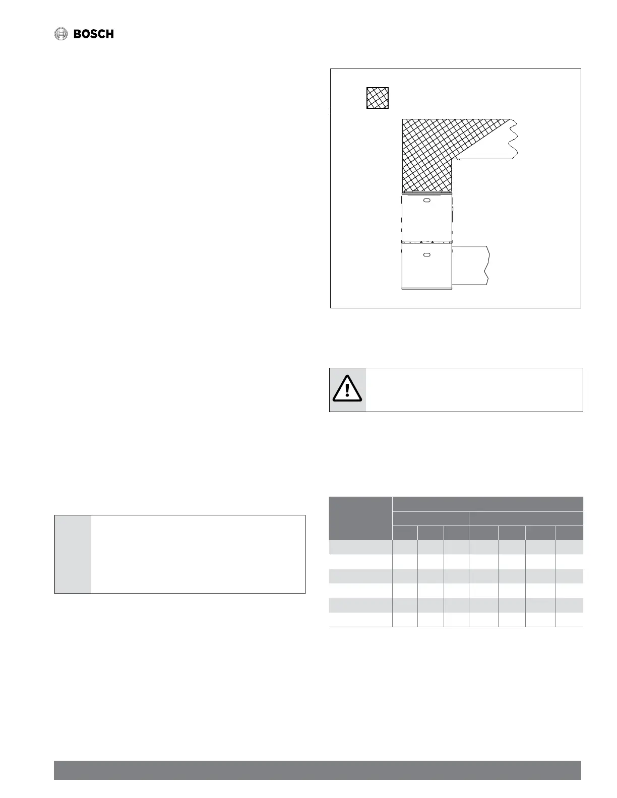
2. Place thermometers in the return and supply ducts as close to the furnace
as possible. Thermometers must not be influenced by radiant heat by being
able to "see" the primary heat exchanger (see Fig. 39).
3. Subtract the return air temperature from the supply air temperature to
determine the air temperature rise. Allow adequate time for thermometer
readings to stabilize.
4. Adjust temperature rise by adjusting the circulator blower speed. Increase
blower speed to reduce temperature rise. Decrease blower speed to
increase temperature rise. Refer to the following section for speed changing
details.
Figure 45
Return Air
Supply Air
HEAT EXCHANGER
RADIATION “LINE OF SIGHT”
Temperature rise measurement
11.8 Circulator Blower Speed Adjustment
WARNING: ELECTRICAL SHOCK HAZARD
f Turn OFF power to the furnace before changing speed taps.
This furnace is equipped with an X13 ECM circulator blower motor. This blower
provides ease in adjusting blower speeds. Refer to the table below for blower speed
factory settings. These blower speeds should be adjusted by the installer to match
the installation requirements so as to provide the correct heating temperature rise
and the correct cooling CFM (Refer to Tables 4 & 5, (pages 24-25) - Air Delivery -
CFM (Without Filter)*.
Model
Default FAN SPEED
DIP SW NOMINAL SPEED
S3-1 S3-2 S3-3 H-heat L-heat H-cool L-cool
BGH96M060B3B OFF ON ON 4 3 5 3
BGH96M080B3B ON OFF OFF 5 3 5 4
BGH96M080C4B ON OFF OFF 5 3 5 4
BGH96M100C5B OFF OFF ON 4 2 3 2
BGH96M100D5B OFF OFF ON 4 2 3 2
BGH96M120D5B OFF ON OFF 4 3 3 2
Table 25 Fan Speed Factory Default Settings