This document provides installation instructions for the CT636LE, CT836LE, and CTL636E series fully automatic coffee machines. It includes safety information, a list of included components for installation, and step-by-step guidance for mounting the appliance.
Function Description
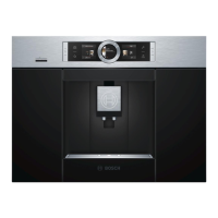
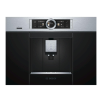
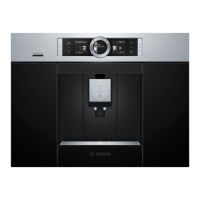
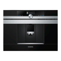
These are fully automatic coffee machines designed for built-in installation. They offer a range of coffee preparation functionalities, though specific features are not detailed in this manual. The installation process focuses on ensuring proper ventilation, secure mounting within a cabinet, and correct electrical connection. The appliance features a door with adjustable opening angles, a drip tray, and an accessories drawer.
Important Technical Specifications
- Dimensions (Appliance):
- Width: 594 mm
- Height: 455 mm
- Depth: 356 mm
- Niche Dimensions (Minimum):
- Width: 560 +8 mm
- Height: 450 +2 mm
- Depth: 400 mm
- Ventilation Requirements:
- A minimum gap of 35 mm must be maintained between the wall and the cabinet base, or the rear panel of the cabinet above.
- Ventilation slots and intake openings must not be covered.
- If installed above a warming drawer, the recess height must be 590 mm.
- If installed directly under a décor panel, a ventilation slot of at least 200 cm² is required.
- The ideal installation height from the floor to the lower edge of the appliance is 950 mm.
- The distance between the appliance and the back wall must be at least 100 mm.
- Door Opening Angles: Three opening angles are selectable:
- Approx. 110° (as delivered): Requires a minimum mounting distance of 350 mm to the left wall.
- Approx. 155°: Requires a minimum mounting distance of 650 mm to the left wall. This involves removing two limits on the upper and lower hinges.
- Approx. 92° (requires special accessory No. 00636455): Requires a minimum mounting distance of 100 mm to the left wall. This involves replacing the two limits on the upper and lower hinges with the specified accessory.
- Electrical Connection: The appliance must be connected and operated according to the type plate specifications. The power cord connects to a standard socket and then securely to the appliance. The mains switch (U) should be set to [O] (off) during installation.
- Magnetic Components: The appliance contains permanent magnets that may influence electronic implants (e.g., pacemakers, insulin pumps). Users with such implants must maintain a minimum distance of 10 cm from the front of the appliance and from specific internal components (milk container, milk system, water tank, brewing unit) when removed.
Usage Features
This manual primarily covers installation, not daily usage. However, it implies the following:
- The appliance has a door that opens to access internal components.
- It includes a drip tray (Y) and an accessories drawer (Z), which are removable.
- A cover (X) on the bottom left-hand side is also removable.
- The appliance has a mains switch (U) for power control.
Maintenance Features
The manual highlights that repairs must only be carried out by authorized customer service personnel to avoid hazards. If the power cord is damaged, it must be replaced with a special connection cord available from after-sales service. No other specific maintenance features are detailed in this installation guide.
Installation Process Overview
- Unpacking and Inspection: Unpack all parts and check for transport damage. Do not operate a damaged appliance.
- Niche Preparation: Ensure adequate ventilation by removing the cabinet's rear panel or cutting a 500 x 400 mm opening. Maintain a minimum 35 mm gap between the wall and cabinet base/rear panel of the cabinet above. Ventilation slots must not be covered.
- Door Opening Angle Adjustment: Select the desired door opening angle (110°, 155°, or 92°) and adjust the hinge limits accordingly. For 155°, remove the limits; for 92°, replace them with special accessory No. 00636455.
- Mounting Bracket Installation: Detach the installation template from the manual's back. Position it at the front edge of the cabinet and screw the assembly bracket (f) with two fastening screws (d) to the cabinet base and wall, ensuring no gap.
- Electrical Connection: Set the mains switch (U) to [O]. Plug the connecting cable (c) into the socket first, then firmly into the appliance. Ensure the cable is not trapped.
- Appliance Insertion: Push the appliance into the cabinet until it clicks into place. Check for central alignment. If needed, pull the appliance out slightly, attach the appropriate spacers (e) to the left side (top and bottom), then push it back in.
- Internal Component Access: Open the appliance door, remove the drip tray (Y), pull out the cover (X) from the bottom left-hand side, and remove the accessories drawer (Z).
- Securing the Appliance: Screw the appliance to the cabinet using fastening screws (d) and sleeves (e) as shown. Then, secure the top right of the unit with one fastening screw (d) and sleeve (e).
- Door Adjustment (Expert Only): In rare cases, if the door jams due to cabinet warpage, it can be adjusted by turning screws (V) for depth and screws (W) for inclination and horizontal position. Hinge dampers must be removed and re-fitted during this process.
- Final Assembly: Reinsert the cover (X) and fix it with two black fastening screws (h). Replace the drip tray (Y) and accessories drawer (Z), then close the appliance door.
- Always read and follow the safety instructions in the instruction manual.
- Danger of electric shock: Connect and operate the appliance only according to type plate specifications. Repairs must be performed by customer service only.
- Damaged power cords must be replaced with a special connection cord available from customer service.
- In case of fault, immediately unplug the appliance or switch off the mains voltage.
- Correct installation according to these instructions ensures safe use.
- Loose furniture must be secured to the wall with a conventional bracket.
- The appliance contains permanent magnets that may affect electronic implants. Maintain a minimum distance of 10 cm from the appliance front and from specific internal components (milk container, milk system, water tank, brewing unit) when removed.