D2212B/D2212BE Operation and Installation Guide
Page 20 © 2002 Bosch Security Systems39934E
D2212B/D2212BE
4.2.6 Battery Discharge/Recharge Schedule (No AC Power)
4.2.6.1 Discharge Cycle:
• AC OFF The keypad indicates trouble. AC Fail reports if programmed.
• 13.9 VDC Charging float level.
• 12.1 VDC Low Battery reports.
• 10.2 VDC Panel shuts down below 10.2 VDC.
4.2.6.2 Recharge Cycle:
• AC ON: Panel restarts, battery charging begins, AC restoral report sent.
• 13.0 VDC Battery restoral reports sent, the keypad returns to normal operation.
• 13.9 VDC Battery float charged.
4.3 Power Outputs
4.3.1 D2212 Circuit Protection
Two self-resetting protection devices protect the panel from short circuits on both the auxiliary and alarm power outputs.
Bell circuit protection: A short on the alarm power output while the bell is ringing disables this output until it times out or
you perform a panel reset.
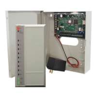
4.3.2 Extra Power for Keypads or Other Powered Devices
You may need to add one or more
D8132 Battery Charger/Power Supply
Modules for the number of keypads
you want to use. Figure 6 shows the
D8132 powering keypads in a stand-
alone configuration.
For UL Certificated accounts, use a
UL Listed power supply. The D8132 is
not UL Listed as a stand-alone power
supply for fire and burglary
applications.
D2212 and D8132 (or other power
supply) must share COMMON: Note
that Figure 6 shows the common from
the D8132 module connected to both keypad’s common and the Aux- (common) terminal on the panel. Do not connect the
stand-alone power supply to earth ground.
4.4 Point Parameters
4.4.1 On-Board Point 1
Point 1 is a powered sensor loop. Review the Bosch Security Systems D2000 Series Control/Communicator Technogram (P/N:
35112) for a list of compatible detectors. Point 1 is supervised with a 2 kΩ EOL resistor.
4.4.2 Points 2 to 6
Points 2 to 6 are supervised with 1.0 kΩ resistors.
• Open Loop: Greater than 8.9 VDC, but less than 13.9 VDC.
• Normal Loop: Greater than 2.5 VDC, but less than 8.5 VDC.
• Shorted Loop: Greater than 0.0 VDC, but less than 2.0 VDC.
4.4.3 Point Response Time
The panel scans point sensor loops every 500 ms. A point must be faulted for two scans (1 sec.) before the panel initiates an
alarm.
Data
+Aux-
Black
(Common)
Green
(Data)
Red
(+12VDC)
D8132 Battery
Charger Module
(Stand-Alone Power
Supply Configuration)
+12VDC Common
Keypad
Connect up to
eight in parallel.
Expanders,
Keypads, RF
Receivers:
Connect up to
eight devices on
the panel.
Up to four devices
can have points
assigned.
Power Module
Figure 6: Power for Keypads