Do you have a question about the Bosch AMC2-4W and is the answer not in the manual?
All safety and operating instructions must be read and followed properly before putting the unit into operation.
Warning! Risk of electric shock. External power supplies must be installed and put into service by qualified personnel.
Check the packaging for visible damage. If anything has been damaged during transport, please inform the transport agency.
Throughout this document, warning messages, important notes, and helpful tips are presented for the reader.
If you are interested in further information on this product or information on other products, please consult our website.
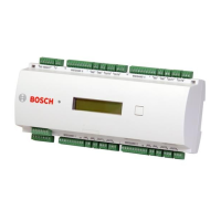
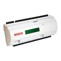
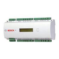
The APC-AMC2-4WCF is equipped with four independent interfaces for Wiegand type readers.
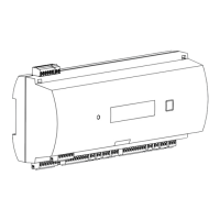
Diagram showing the upper circuit board with display and labels for components like DIL switch, battery, etc.
Lists features like number of entrances, host interfaces, relay outputs, analog inputs, and transfer rates.
Describes how the Access Controller AMC2-4W connects to management host systems and peripheral devices.
Instructions for attaching the AMC2-4W to a standard 35 mm mounting rail using a snap-in mechanism.
Provides instructions on how to remove the AMC2-4W from a mounting rail, including unplugging connectors.
Details the procedure for opening the AMC2-4W case, which involves pushing snap-ins and swinging the cover down.
Explains how to close the AMC2-4W case by aligning hooks and snap-ins, reversing the opening process.
Instructions on routing cables and calculating conductor data for power supply connections to prevent interference.
Guidance on the main grounding point and creating central ground or shielding points using jumpers.
Explains jumper settings for grounding the RS-485 host interface, managing internal and signal grounds.
Details on jumper settings for grounding the AMC2-4W to the RS-485 ground of the slave interface.
Instructions for connecting the external power supply to the 7-pin pluggable screw connector.
Information on connecting the AMC2-4W to a LAN or host computer using its 10/100 Mbit/s Ethernet interface.
Details on configuring an RS-485 host system, including connection types and bus system conditions.
Illustrates the jumper settings for establishing an RS-485 two-wire connection.
Illustrates the jumper settings for establishing an RS-485 four-wire connection, noting crosslink setup.
Details on connecting the AMC2-4W to a host computer or serial modem using the RS-232 interface.
Explanation of DIL switches for configuring host settings like address, protocol, and connection type.
Describes how the RS-485 Extension Module Bus expands functionality with additional I/O modules.
Information on connecting up to four readers with Wiegand interfaces using pluggable screw connectors.
Details on connecting the AMC2-4W's eight form C relay outputs to operate locks or alarm systems.
Instructions for connecting the AMC2-4W's 8 analog inputs to detect lock status or control mechanisms.
Details on connecting external tamper contacts to protect the AMC2-4W against unauthorized access.
Explains how the liquid crystal display shows status information and how to switch between modes using the 'Dialog' button.
Guidance on using the AmclpConfig tool to configure the AMC2-4W in a TCP/IP network environment.
Steps for diagnosing issues, including checking connections, IP address, DIL switch settings, and resetting.
Procedure for resetting the AMC2-4W software by pressing the reset button for three seconds.
Instructions for performing a factory default reset by opening the case, setting DIL switches, and pressing the reset button.
Diagrams showing connectors for RS-485 Host, RS-232, and Ethernet interfaces on the upper PCB.
| Series | AMC2 |
|---|---|
| Audio Inputs | 4 |
| Audio Outputs | 4 |
| Input voltage | 24 VDC |
| Number of outputs | 4 |
| Protection class | IP30 |
| Operating temperature | -10°C to +55°C |
| Type | Controller |
| Output current | 0.5 A per output |
| Weight | 0.5 kg |


