Equipment Configuration
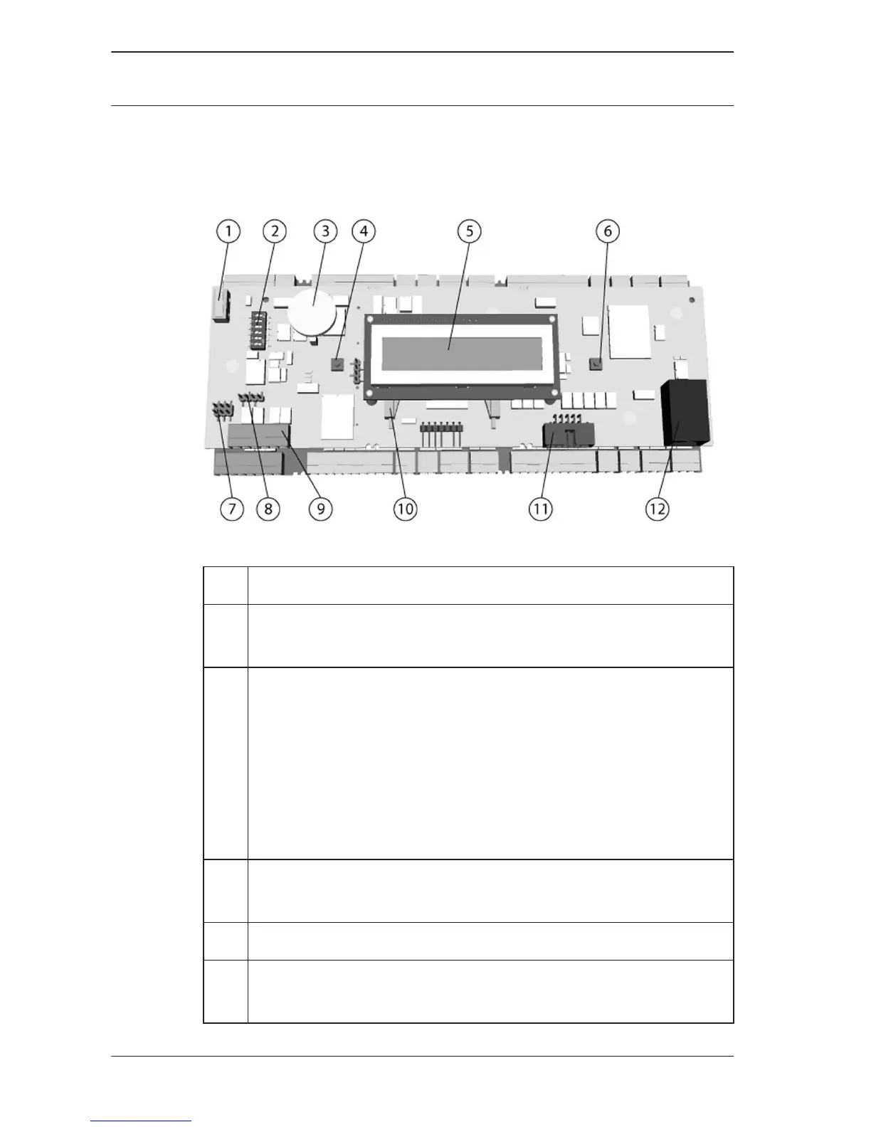
Figure 3.3: Upper circuit board with display (top side)
1
(N.A.)
2 DIL switch for RS-485 address selection , protocol, and
RS-232/RS-485 selection.
3 Lithium battery for buffering of static RAM and real time
clock (RTC). The battery life is estimated at 10 years,
nevertheless an error message is generated if the voltage
sinks below a preset minimum level.
NOTICE: In order to avoid an error message caused by an
earlier voltage drop we suggest to replace the battery
every 8 years. Spare part: VARTA CR 2032 PCB.
4 Reset push button - reachable through the casing using a
screwdriver
5 Liquid Crystal Display
6 Push button, available on top of the housing, to select
different display modes
3.2
14 en | Introduction
Access Modular
Controller
2016-11 | AMC2-4W | Bosch Sicherheitssysteme