How to fix a Bosch Access Modular 2 when the display is not working?
- DDanielle OwensSep 12, 2025
If the Bosch Controller display is not working, ensure that the power supply provides sufficient voltage. Also, make sure the controller is powered on.
How to fix a Bosch Access Modular 2 when the display is not working?
If the Bosch Controller display is not working, ensure that the power supply provides sufficient voltage. Also, make sure the controller is powered on.
What to do if my Bosch Controller is not online?
If your Bosch Controller is not online, first, plug the Ethernet cable into the controller to establish a network connection. Second, check the DIP switch 5 setting. If it's set to OFF (BPA protocol), set it to ON (SDEB protocol).
Why doesn't my Bosch Controller work as expected?
If the Bosch Controller does not work as expected, try these steps: 1. Switch the power of the controller off and on again. 2. Check the configuration of the controller. If necessary, delete all configuration data by Resetting the Device to Factory Default. 3. Reset the controller as described in Resetting the software.
What to do if there is no connection to BIS and AMS after a factory reset on a Bosch Access Modular 2 Controller?
If you're experiencing no connection to BIS and AMS after a factory reset on your Bosch Controller, it might be due to the following reasons: There is no connection to access system, so check the configuration settings within the AMS or ACE system. Also, verify that the controller is activated in the configuration settings.
What to do if there is no connection to BIS and AMS after a factory reset of Bosch Controller?
If you have no connection to BIS and AMS after a factory reset on your Bosch Controller: * Check the configuration settings within the AMS or ACE system to ensure there is a connection to the access system. * Verify that the controller is activated in the configuration settings.
What to do if Bosch Access Modular 2 Controller is not online?
If your Bosch Controller is not online, there are a few potential causes. First, ensure the Ethernet cable is properly plugged into the controller. Second, check the DIP switch 5 setting; if it's set to OFF (BPA protocol), set it to ON (SDEB protocol). Also, make sure to configure the Ethernet interface correctly.
Why is the display not working on my Bosch Access Modular 2 Controller?
If the display on your Bosch Controller isn't working, it could be due to a couple of reasons. Ensure that the power supply provides sufficient voltage to power the controller. Also, verify that the controller is powered on.
How to fix a Bosch Access Modular 2 that does not work as expected?
If your Bosch Controller isn't working as expected, try these steps: First, switch the power of the controller off and on again. Second, check the configuration of the controller, and if necessary, delete all configuration data by resetting the device to factory default. Also, reset the controller as described in Resetting the software.
What to do if Bosch IP Access Controller does not work as expected?
If your Bosch IP Access Controller isn't working as expected, try these steps: First, switch the power of the controller off and on again. If the problem persists, check the configuration of the controller and if necessary, delete all configuration data by resetting the device to factory default. As a last resort, reset the controller as described in Resetting the software.
Why is my Bosch IP Access Controller not online?
Your Bosch IP Access Controller might not be online due to a missing network connection. Ensure the Ethernet cable is securely plugged into the controller. Also, check the DIP switch 5 setting. If it's set to OFF (BPA protocol), set it to ON (SDEB protocol).
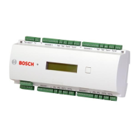
Provides a general overview of the Access Modular Controller 2's capabilities and features.
Details the components and layout of the main circuit board, including DIP switches and connectors.
Outlines how the controller connects to the host system and its overall architecture.
Instructions for attaching the controller to a standard 35 mm mounting rail securely.
Steps for safely removing the controller from its mounting rail.
Procedure for opening the controller's housing to access internal components.
Steps for properly reassembling the controller's housing after maintenance.
Guidelines and data for connecting cables, including power and data connections.
Procedures for grounding and shielding the controller to ensure electrical safety and signal integrity.
How to connect an external power supply to the controller using the pluggable screw connector.
Details on connecting the controller to a network via its Ethernet interface.
Information on configuring and connecting the controller using the RS-485 host interface.
Connecting additional I/O modules to the AMC2 using the RS-485 extension module bus.
Details on connecting card readers using the four RS-485 interfaces provided.
How to connect external devices to the controller's eight relay outputs.
Instructions for connecting devices to the controller's eight analog inputs.
Information on connecting external tamper contacts to protect the AMC2 from unauthorized access.
Steps for configuring the controller's Ethernet interface using the IPConfig tool.
Outlines the system requirements for UL compliance, including host systems and readers.
Explains the different UL 294 security levels relevant to access control products.
Detailed instructions for installing the system to meet UL requirements and restrictions.
Provides extended technical details, including specifications for RS-485 extension and power consumption.
Step-by-step guide to reset the controller's software using the reset button.
Procedure for resetting the entire device to its factory default settings, including network configuration.
Visual diagrams showing the physical connections for RS-485 and Ethernet interfaces on the PCB.
Information on the controller's status display, detailing various firmware versions and their output.
| Model | Access Modular Controller 2 |
|---|---|
| Number of Doors Supported | 2 |
| Enclosure Rating | IP30 |
| Number of Outputs | 4 |
| Communication Protocol | TCP/IP |
| Connectivity | Ethernet |
| Current Consumption | 500 mA |
| Humidity | non-condensing |
| Number of Inputs | 8 |
| Compatibility | Bosch Access Management Software |
| Input Voltage | 12 to 24 VDC |
