Access Modular Controller 2 Appendices | en 45
Bosch Security Systems B.V.
Guide d'installation
2022-11 | V04 |
11 Appendices
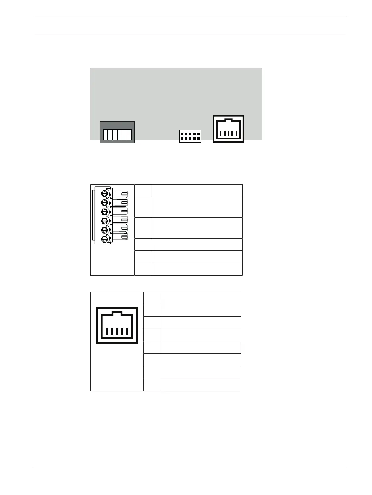
11.1 Connecting diagrams
RS485 Host
RS232
Ethernet RJ45
1 2 3 4 5 6
1
2
3
4
5
6
7
8
9
10
8 4 1
Figure11.1: Connectors on upper PCB
The RS-485 interface is not supported by:
– BIS 4.9.1 and later
– AMS 4.0 and later.
1 NC (configurable shield)
2 Data RxTx+ (2-wire)
Data Rx+ (4-wire)
3 Data RxTx- (2-wire)
Data Rx- (4-wire)
4 PAG
5 Data Tx+ (4-wire)
6 Data Tx- (4-wire)
Table11.4: RS-485 host on upper PCB
1 TXD+
2 TXD-
3 RXD+
4 Not connected
5 Not connected
6 RXD-
7 Not connected
8 Not connected
Table11.5: Ethernet Network socket (RJ45)