EasyManua.ls Logo

Bosch Access Modular Controller 2 User Manual

Bosch Access Modular Controller 2
56 pages
To Next Page IconTo Next Page
To Previous Page IconTo Previous Page
Page #18 background image
18 en | Installing Access Modular Controller 2
2022-11 | V04 |
Guide d'installation
Bosch Security Systems B.V.
4.6 Grounding and shielding
The main grounding point at the controller is connected to pin 2 of the power supply
connector.
For more information on these connections, refer to
Connecting diagrams, page 45
.
It is good practice to shield all wires carrying low level signals.
The controller allows you to create a central ground or shielding point, simply by setting
certain jumpers. Set these jumpers only if grounding or shielding is not achieved by other
means.
i
Notice!
The functional earth ground symbol identifies a functional part that allows installing an
electrical system in an electromagnetically compatible manner.
i
Notice!
Risk of malfunction
Ensure that no ground loops are formed.
i
Notice!
In general the following apply:
If the devices have their own power supplies, the shielding is applied to one side only. The
free end should be insulated to avoid inadvertent connections.
If one device is fed power by another, the cable shielding should be applied to both sides.
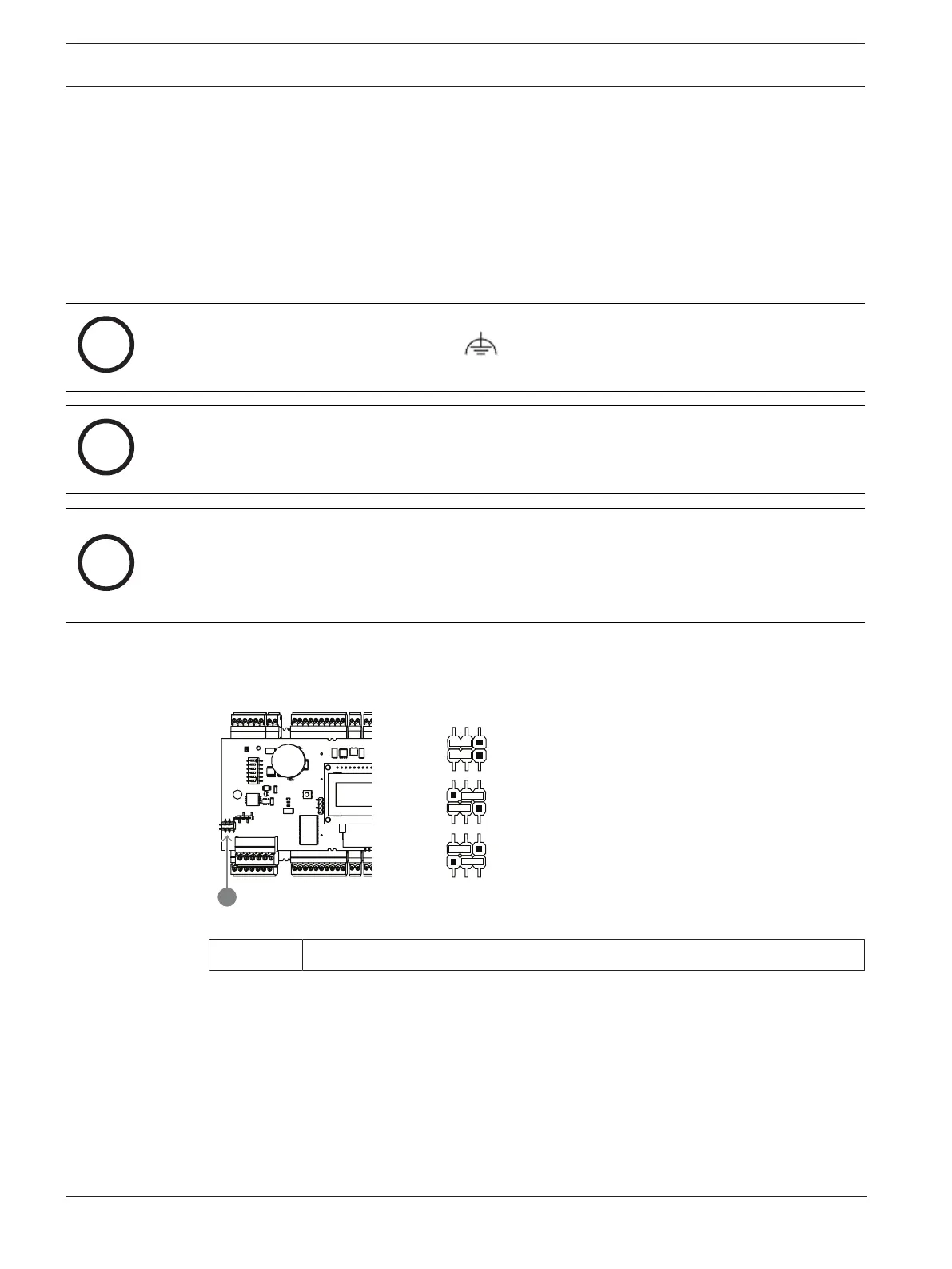
4.6.1 Grounding for host interface
A 1:
A 2:
A 3:
JP1
JP2
JP1
JP2
A
Figure4.5: Location of ground jumper RS-485 host interface
A1 Delivery status
The internal ground of the controller is always connected with the ground of the RS485 host.
The jumper setting A1 shows the factory settings.
Jumper JP1 connects the internal ground of the controller to the ground of the RS-485 host
interface.
Jumper JP2 manages the signal ground.
Settings for jumper JP1:
If the ground conductor and the shield on the host are not connected and:
no party line exists, the jumper JP1 is set (=A2)
a party line exists, the jumper JP1 is set at the first device only (=A2)

Other manuals for Bosch Access Modular Controller 2

Questions and Answers:

Bosch Access Modular Controller 2 Specifications

General IconGeneral
ModelAccess Modular Controller 2
Number of Doors Supported2
Enclosure RatingIP30
Number of Outputs4
Communication ProtocolTCP/IP
ConnectivityEthernet
Current Consumption500 mA
Humiditynon-condensing
Number of Inputs8
CompatibilityBosch Access Management Software
Input Voltage12 to 24 VDC

Summary

Safety

Short Information

Introduction

Description (3.1)

Provides a general overview of the Access Modular Controller 2's capabilities and features.

Product Overview (3.2)

Details the components and layout of the main circuit board, including DIP switches and connectors.

System Overview (3.3)

Outlines how the controller connects to the host system and its overall architecture.

Installing

Mounting the Device on a Mounting Rail (4.1)

Instructions for attaching the controller to a standard 35 mm mounting rail securely.

Unmounting the Device from a Mounting Rail (4.2)

Steps for safely removing the controller from its mounting rail.

Opening the Case (4.3)

Procedure for opening the controller's housing to access internal components.

Closing the Case (4.4)

Steps for properly reassembling the controller's housing after maintenance.

Cabling (4.5)

Guidelines and data for connecting cables, including power and data connections.

Grounding and Shielding (4.6)

Procedures for grounding and shielding the controller to ensure electrical safety and signal integrity.

Connecting the Power Supply to the Controller (4.7)

How to connect an external power supply to the controller using the pluggable screw connector.

Ethernet Host Interface (4.8)

Details on connecting the controller to a network via its Ethernet interface.

RS-485 Host Interface (4.9)

Information on configuring and connecting the controller using the RS-485 host interface.

RS-485 for Extension Modules (4.10)

Connecting additional I/O modules to the AMC2 using the RS-485 extension module bus.

RS-485 Interface for Card Readers (4.11)

Details on connecting card readers using the four RS-485 interfaces provided.

Connecting Relay Outputs (4.12)

How to connect external devices to the controller's eight relay outputs.

Connecting Analog Input Devices (4.13)

Instructions for connecting devices to the controller's eight analog inputs.

Tamper Protection (4.14)

Information on connecting external tamper contacts to protect the AMC2 from unauthorized access.

Operating

Configuring Ethernet Interface (5.1)

Steps for configuring the controller's Ethernet interface using the IPConfig tool.

UL Requirements

System Requirements (6.1)

Outlines the system requirements for UL compliance, including host systems and readers.

UL 294 Level Descriptions (6.2)

Explains the different UL 294 security levels relevant to access control products.

Installation Instructions (6.3)

Detailed instructions for installing the system to meet UL requirements and restrictions.

Extended Technical Specification (6.4)

Provides extended technical details, including specifications for RS-485 extension and power consumption.

Troubleshooting

Resetting the Software (7.1)

Step-by-step guide to reset the controller's software using the reset button.

Resetting the Device to Factory Default (7.2)

Procedure for resetting the entire device to its factory default settings, including network configuration.

Service and Repair

Disposal

Technical Specifications

Appendices

Connecting Diagrams (11.1)

Visual diagrams showing the physical connections for RS-485 and Ethernet interfaces on the PCB.

Status Display (11.2)

Information on the controller's status display, detailing various firmware versions and their output.

Related product manuals