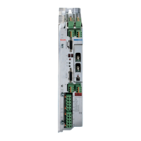
Do you have a question about the Bosch Rexroth Diax 04 and is the answer not in the manual?
Critical safety information, hazards, and precautions for personnel and equipment operation.
Defines the intended applications and operating conditions for the drive controller as per reference documentation.
Explains how to identify product models through type codes and product type plates.
Lists the components included with the drive controller, such as cables and connectors.
Provides detailed electrical and mechanical ratings for specific HDD and HDS drive controller models.
Illustrates required mounting distances and airflow paths for proper installation and cooling of the drive controller.
Lists related technical documents and manuals for the drive controller system and associated products.
Details safety precautions and requirements for implementing overcurrent protection for the drive system.
Presents wiring diagrams for the HVE supply unit and general connection principles.
Illustrates the electrical wiring configuration for the HVR supply unit, including control cabinet connections.
Shows detailed electrical connection diagrams for HDS drive controllers, including interfaces and modules.
Shows detailed electrical connection diagrams for HDD drive controllers, including interfaces and modules.
Details connection interfaces like X1 and X5, including specifications and cross-sections.
Details connection cross-sections, tightening torques, and design for the X5 connector for DC bus and motor connections.
Explains grounding methods, motor power cable composition, and DC bus voltage connection guidelines.
Details connections for the X6 connector for holding brakes and motor temperature monitoring, including their control.
Describes power supply connection methods based on unit arrangement (horizontal/vertical) and related cable requirements.
Provides general installation guidelines and critical safety information, including ESD precautions.
Discusses control cabinet sizing, component layout, cooling strategies, and moisture condensation prevention.
Explains the process and safety measures required for discharging energy stored in DC bus capacitors.
Details the operating principle, dimensioning, and step-by-step procedure for using the discharging device.
| Manufacturer | Bosch Rexroth |
|---|---|
| Category | Controller |
| Supply Voltage | 24 VDC |
| Control Type | Digital |
| Protection Class | IP20 |
| Series | Diax |


