EasyManua.ls Logo

Bosch EP Series User Manual

Bosch EP Series
44 pages
To Next Page IconTo Next Page
Page #1 background imageLoading...
Page #1 background image
Installation and Maintenance Manual
EP Series
8733953041 (2019/01)
EP007, EP009, EP012, EP015, EP018, EP024, EP030, EP036, EP042, EP048, EP060,EP070
Question and Answer IconNeed help?

Do you have a question about the Bosch EP Series and is the answer not in the manual?

Bosch EP Series Specifications

General IconGeneral
SeriesEP Series
Operating Temperature Range (Heating)-20°C to 24°C
Dimensions (Outdoor Unit)Varies by model, consult product specifications
Weight (Outdoor Unit)Varies by model, consult product specifications
Operating Temperature Range (Cooling)10°C to 46°C

Summary

INSTALLATION

MOUNTING VERTICALLY

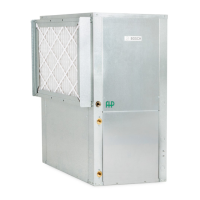
Mounting procedures for vertical units, focusing on level placement and vibration.

MOUNTING HORIZONTALY

Suspension instructions for horizontal units, including ceiling anchor requirements.

HANGING BRACKET KIT

CONDENSATE DRAIN

DUCT SYSTEM

PIPING

ELECTRICAL

THERMOSTAT CONNECTIONS

ECM INTERFACE BOARD AND TERMINALS

ECM Interface Board overview, connections, and terminal functions.

THERMOSTAT CONTROL SETTINGS

SAFETY DEVICES AND THE UPM CONTROLLER

UPM BOARD CONNECTIONS AND INDICATORS

UPM board connections for safety sensors and inputs, plus status LED indicators.

UPM CONTROLLER FEATURES

SAFETY FEATURES AND OPERATING MODES

Explains UPM safety features: anti-short cycle, random start, low pressure bypass, brownout.

ELECTRONIC THERMOSTAT INSTALLATION

THERMOSTAT WIRING DIAGRAMS

Typical thermostat wiring connections for cooling and heating modes.

UPM SEQUENCE OF OPERATION

ELECTRIC HEATER PACKAGE OPTION

WATER QUALITY

HEAT RECOVERY PACKAGE

TYPICAL CONNECTION PIPING (HRP)

Details on preparing the water tank and piping connections for the HRP.

WATER TANK REFILL

INITIAL START-UP

HOT GAS REHEAT (HGRH)

SEQUENCE OF OPERATION

COOLING AND HEATING MODES

Details operational sequences for cooling and heating, including fan and compressor stages.

APPLICATION CONSIDERATIONS

WELL WATER SYSTEMS GUIDANCE

Guidance for well water systems, emphasizing testing and flow for heat pumps.

INSTALLATION OF PRESSURE REGULATING VALVES

COOLING TOWER/BOILER SYSTEMS

GEOTHERMAL (EARTH-COUPLED) SYSTEMS

SYSTEM CHECKOUT

UNIT START-UP

MAINTENANCE

FILTER CHANGES AND CLEANING

Filter replacement frequency guidance based on environmental conditions.

TROUBLESHOOTING

UPM BOARD LED INDICATIONS

UPM board LED colors and blink codes for fault identification.

UNIT TROUBLESHOOTING

HRP TROUBLESHOOTING

STANDARD MOTOR-PSC

STANDARD MOTOR-PSC DATA

CONSTANT CFM MOTOR SELECTION

STANDARD MOTOR-PSC PERFORMANCE

EP MOTOR-CFM SELECTION

WATER SIDE PRESSURE DROP

AIR TEMPERATURE RISE/FALL

REFRIGERANT PRESSURE RANGES

VERTICAL DIMENSIONS

HORIZONTAL DIMENSIONS

WIRING DIAGRAMS

UPM STATUS LED - BLINK CODES

Explains blink codes for UPM status LEDs to identify faults.

WIRING DIAGRAMS: COMPONENT LEGENDS

WIRING DIAGRAMS: UPM I MODULE

WIRING DIAGRAMS: MOTOR SELECTION

WIRING DIAGRAMS: HEATER PACKAGE

ELECTRIC HEAT WIRING DIAGRAM

Related product manuals