Installation Instructions Linear Smoke Detector Fireray 50/100RV
ST/PMF/zab
610-F.01U.002.706 / A2.en
Page 6 of 14
1
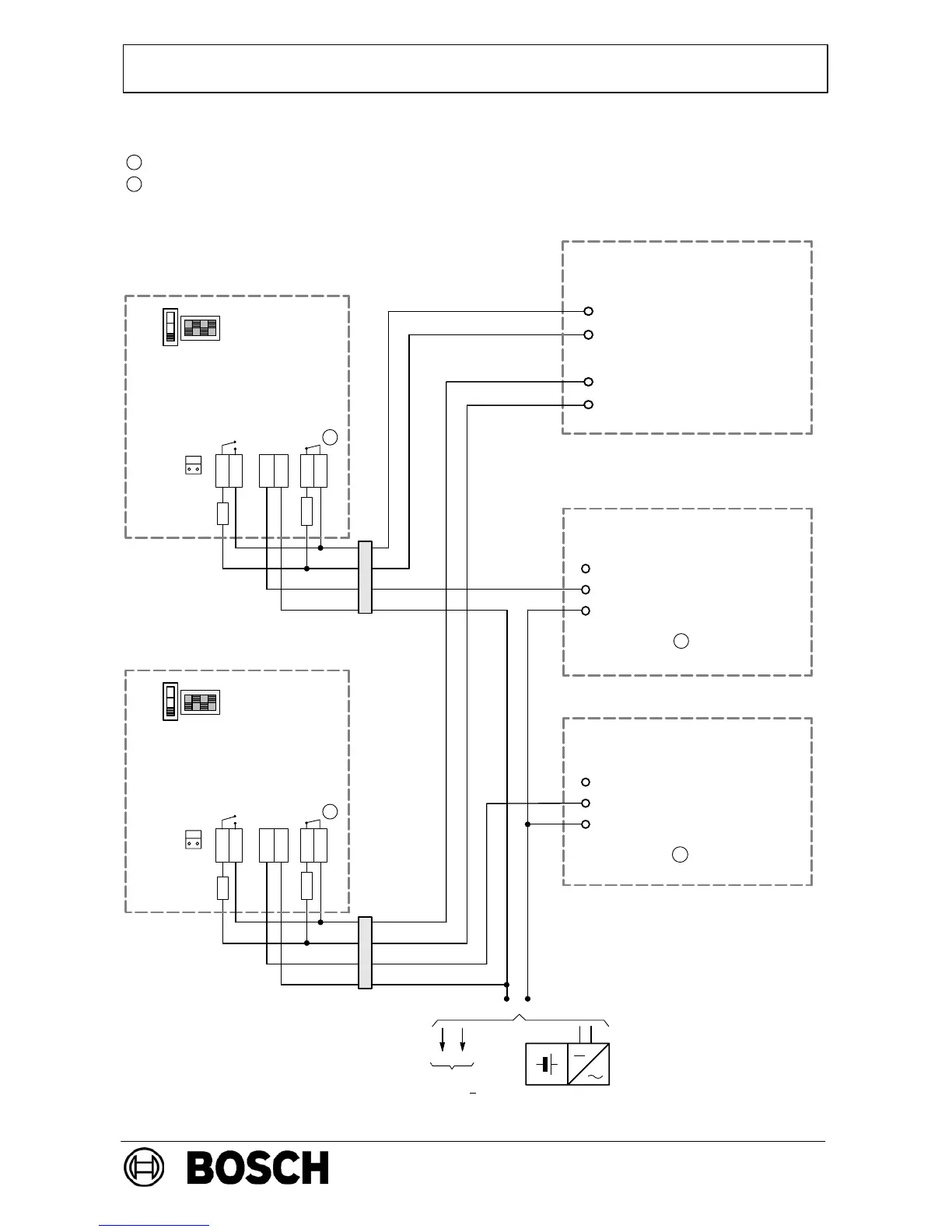
Bridges Br1, Br2 on the NSB 100 in position 2-3 (see connection of one Fireray 50/100RV)
FAULT
ALARM
Power sup-
ply 10 - 30
V
Fireray 50/100 RV
rd
bl
NO
COM
NC
COM
ye
blk
gn wh
2
2
Contacts in open position
Configuration for LSN:
Parameterize the NSB in the control panel to control output
KA1-KA2/KR-R-RR and “Control with Fireray”.
Observe assignment to detector groups/detectors (see example).
Output
for key switch
(optional)
Operating mode
switch
DIP switch
(recommended
settings)
+
820
Connection of two Fireray 50/100RV to fire panel with cross zoning via an NBK
100 LSN and two NSB100 LSNs
V1
V2
Line 2
VI1
VI2
Line 1
V1
V2
Line 2
VI1
VI2
Line 1
NBK 100 LSN
NSB 100 LSN
V1 KR
V2 KA1
V3 KA2
NSB 100 LSN
V1 KR
V2 KA1
V3 KA2
3k92
FAULT
ALARM
Power sup-
ply 10 - 30
V
Fireray 50/100 RV
NO
COM
NC
COM
2
Operating mode
switch
820
3k92
Parameterize, e.g. to 127/1
Parameterize, e.g. to
KA1-KA2-KR-150/2
Parameterize, e.g. to
KA1-KA2-KR-500/2
-
+
-
rd blk
bl ye gn wh
(if voltage drop < 6V)
-U +U
-U +U
I3 I4
NSB 100
EV 24 V - 24 V
150/1 cross zoning with 500,
current trigger criterion
6 DA mini
distributor
6 DA mini
distributor
Output
for key switch
(optional)
Parameterize, e.g. to 127/2
Parameterize, e.g. to 127/3
500/1 cross zoning with 150,
current trigger criterion
1
1
DIP switch
(recommended
settings)
 Loading...


