Applications Manual Bosch Greenstar | 41
Bosch Thermotechnology Corp.
Data subject to change
Neutral
120 V Line
Ground
See CZM100
Manual for
Detail wiring
CRC100 or CRC200
CZM100
Bosch Bosch
VZ3
VZ1
T0
24VAC
VZ2
1
2
1
21
2
1
21
23
4
3
4
3
4
24 VAC
Transformer
2-wire, 3 -wire and 4- wire zone valves
120 Vac
24 Vac
PZ3
PZ2
PZ1
120 VAC
L
NL
N
L
N
L
N
< 24 V
BUS
1
21
21
21
2
BUS
BUS BUS
120 VAC
Bosch
1
4
5
6
0
3
2
1
2 3 4
System # 18
reset
eco
1
2
34
5
6
max
1
2
34
e
6
max
DHW thermostat
min
e
max
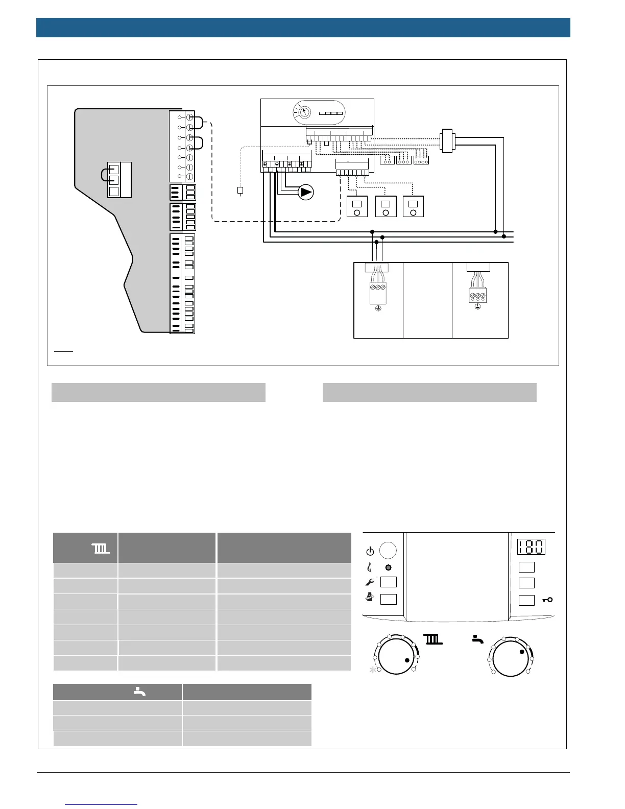
Typical DHW temperatures
approx. 104 °F (40 °C)
approx. 122 °F (50 °C)
approx. 140 °F (60 °C)
Boiler
Heating
Dial
1
2
3
Typical supply
temperatures
approx. 95 °F (35 °C)
approx. 109 °F (43 °C)
approx. 122 °F (50 °C)
4
5
6
approx. 140 °F (60 °C)
approx. 153 °F (67 °C)
approx. 167 °F (75 °C)
max Approx. 194 °F (90°C)
Application
Frost protection
Radiant floor heating
Panel radiator system
Cast Iron radiator system
Baseboard & convector system
Heatronic Settings:
Low Voltage
Wiring:
Line Voltage
Heatronic Internal Wiring
B
B
4
2
1
A
F
9
7
8
LWCO
Supply Sensor
Dry contacts
Bosch Controls
Outdoor
Sensor
Ź Wire BUS terminal of CZM100 to Terminal BB of
Greenstar boiler Heatronic control
Ź Wire Main power supply (120 v) to White molex
of Boiler (external junction box) and to 120 VAC
input of CZM100
Ź Wire CRC controllers to BUS terminals of CZM100
(See Appendix A for Room Controller Settings)
Ź Wire 120 VAC ouput of PZ1 to system pump
Ź Provide 24 Vac from transformer to Terminals 1
and 2 of CZM100 labeled “24 VAC”
ŹWire zone valves to “VZ” terminals of CZM100 –
remove jumper from terminal 3 and 4 for 3-wire and
4-wire zone valves
Ź Wire Supply Sensor to “TO” connection of CZM100
L
N
black
ch pump
for unmixed heating
(Not Used)
L
N
white
mains
120v/60 hz
Note: For Low Water Cutoff Wiring see
Appendix D of this manual
Supply Sensor