Do you have a question about the Bosch Greenstar FS Series and is the answer not in the manual?
Explains the meaning of signal words used in warnings and their associated risks.
Provides essential safety procedures for gas leaks, smell of gas, and flue gas.
Highlights safety precautions for soldering and brazing near flammable materials.
Details safety measures related to flue gas and venting systems to prevent poisoning.
Outlines safety requirements for working with gas components and installation.
Warns about combustible materials in the boiler room and clearance requirements.
Advises on keeping combustion air free from corrosive substances and dust.
Emphasizes disconnecting power before any work and using qualified electricians.
Instructs not to shut off safety valves and warns about hot water escape.
States that flooded appliances must be replaced and not operated.
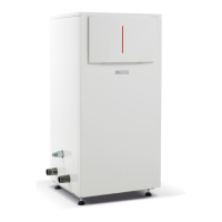
Details the contents of the package for KBR heating boilers.
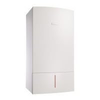
Details the contents of the package for KWB combi boilers.
Specifies that the appliance is for closed-loop hot water heating systems only.
Explains the meaning of model numbers and appliance types (KBR/KWB).
Describes the location and information found on the appliance's rating plate.
Lists key features and components of the appliance, including Heatronic control.
Mentions typical accessories available for the appliance and refers to the product catalog.
Provides detailed dimensions and required clearances for installation.
Diagram showing the internal layout and numbered components of the KBR heating boiler.
Diagram showing the internal layout and numbered components of the KWB combi boiler.
Wiring diagram for the KBR heating boiler, showing connections and components.
Wiring diagram for the KWB combi boiler, showing connections and components.
Provides detailed technical specifications for the KBR 16-3 heating boiler.
Provides detailed technical specifications for the KBR21-3 heating boiler.
Provides detailed technical specifications for the KBR 28-3 heating boiler.
Provides detailed technical specifications for the KBR 35-3 heating boiler.
Provides detailed technical specifications for the KBR 42-3 heating boiler, including altitude adjustments.
Provides detailed technical specifications for the KWB 28-3 combi boiler.
Provides detailed technical specifications for the KWB 35-3 combi boiler.
Provides detailed technical specifications for the KWB 42-3 combi boiler, including altitude adjustments.
Lists typical ingredients and concentrations found in boiler condensate.
Outlines compliance with national and local codes, standards, and regulations for installation.
Specifies the maximum boiler temperature and operating pressure limits.
Details specific requirements for installations in Massachusetts, including CO detectors and signage.
Describes piping configurations for multi-zone systems using zone valves and DHW.
Step-by-step guide on how to utilize the Low Loss Header (LLH) for hydraulic separation.
Wiring diagram for multi-zone systems with zone valves and LWCO, referencing control modules.
Describes piping configurations for multi-zone systems using circulators and DHW.
Step-by-step guide on how to utilize the Low Loss Header (LLH) for hydraulic separation.
Wiring diagram for multi-zone systems using circulators, referencing control modules.
Provides crucial installation notes, including filling the system and recommended commissioning steps.
Details important installation considerations like venting, plastic pipework, and room controllers.
Guides on verifying expansion vessel capacity and determining if an additional vessel is needed.
Instructions for selecting an external expansion vessel for KBR heating boilers.
Provides requirements for selecting the installation location and notes on combustion air.
Details installation location requirements and notes on combustion air, including corrosive materials.
Explains the use of a Low Loss Header (LLH) for hydraulic separation and flow rate management.
Provides step-by-step instructions for utilizing the Low Loss Header (LLH).
Provides instructions for locating and positioning the appliance, including removing the cover.
Details how to level the boiler for proper air escape and condensate drainage.
Guides on installing the LWCO device, specifying approved models and requirements.
Explains how to connect optional vent systems like twin pipe and concentric venting.
Instructions for attaching the vent flange and gasket when using the twin pipe adapter.
Provides critical safety warnings regarding carbon monoxide poisoning and proper venting.
Lists essential requirements for direct vent installations, including pipe support and termination clearances.
Shows approved examples of venting systems and provides installation notes.
Details maximum vent and combustion pipe lengths based on appliance, elbows, and pipe type.
Explains access to installer junction boxes for high and low voltage connections.
Locates the high voltage and low voltage junction boxes for electrical connections.
Instructions for connecting Bosch room controls to the boiler's internal BUS system.
Details connections for mains power, system circulator pump, and DHW tank circulator pump.
Guides connecting external pumps and setting their function via service functions.
Instructions for connecting DHW tank pumps or 3-way valves for KBR heating boilers.
Details the procedure for connecting the mains power supply cable to the boiler.
Explains the low voltage junction box connections for sensors, thermostats, and programmers.
Instructions for connecting external safety switches like high limit or LWCO.
Guides on connecting the DHW tank temperature sensor to the low voltage connections.
Step-by-step instructions for connecting the LWCO device, including transformer and wiring.
Provides pre-operation checks, including filling, purging, and gas type verification.
Explains how to switch the appliance on and off using the ON/OFF switch and what the display shows.
Guides on setting the maximum supply temperature based on the building's heat loss.
Refers to the room controller's operating instructions for setup, mode adjustment, and mounting.
Lists post-commissioning checks including flue path tightness, gas pressure, and condensate discharge.
Instructions for setting the DHW temperature on the thermostat for KBR heating boilers.
Instructions for setting the DHW temperature on the thermostat for KWB combi boilers.
Explains DHW priority, alternating operation, and comfort vs. economy modes.
Describes setting manual summer mode to switch off heating while keeping DHW active.
Provides procedures for setting frost protection for the heating system and DHW tank.
Explains how to activate and unlock the key pad lock to prevent unauthorized access.
Covers thermal disinfection for DHW systems, excluding solar tanks.
Warns about scalding risk from hot water and advises on disinfection procedures.
Explains the function that prevents the heating zone pump from seizing during idle periods.
Guides on how to change the boiler pump speed using the dial on the pump.
Introduces the Heatronic control and its service functions, divided into two levels.
Provides an overview of available service functions, categorized by first and second service levels.
Lists and describes service functions from 1.A to 7.E, including their purpose and default settings.
Provides descriptions for specific service functions, including limitations and system requirements.
Explains how to access and set service functions for maximum outputs and pump modes.
Allows displaying the current DHW temperature.
Allows displaying the temperature of the DHW tank sensor.
Sets DHW heating delay for solar thermal systems to prevent unnecessary boiler operation.
Shows current heat demand status: no demand, space heating, or DHW demand.
Warns about dangers of improper conversion, including fire, explosion, and carbon monoxide.
Explains the derating of input/output rates at higher altitudes and altitude adjustment.
Guides on setting the gas/air ratio using an electronic flue gas analyzer and test ports.
Provides instructions for performing a dynamic gas pressure test and checking inlet gas pressure.
Explains how to use the emissions test button to select different output modes for testing.
Guides on measuring CO levels in flue gas, including safety warnings for CO poisoning.
Highlights Bosch's commitment to environmental protection in product design and packaging.
Introduces the importance of regular service and maintenance for appliance longevity and efficiency.
Explains how to access the latest fault code using service function 6.A.
Guides on how to remove, clean, or replace the fresh water filter in the cold water pipe.
Provides instructions for inspecting and descaling or replacing the plate type heat exchanger.
Guides on how to remove, check, and reinstall the electrode set.
Provides safety warnings regarding burner operation and step-by-step instructions for removing the burner cover.
Details the inspection and cleaning procedure for the heat exchanger block, using specific tools.
Guides on removing, cleaning, and reinstalling the condensate trap, including filling with water.
Explains how to open the mixer unit and check the diaphragm for contamination or cracks.
Details the annual inspection requirement for the expansion vessel and how to adjust its pre-charge pressure.
Provides a table of operating pressures and guides on topping up water and checking for leaks.
Explains how to test system water quality using pH meters and the necessary actions if values are outside the range.
Advises on checking electrical wiring for mechanical damage and replacing defective cables.
Provides a checklist to guide through the annual service and maintenance procedure, recording findings.
Explains the various readings shown on the 7-segment display, including service functions and fault codes.
Provides basic troubleshooting steps for common hazards like explosion, flue gas poisoning, electric shock, and freezing.
Warns about scalding risk from hot water and advises draining the appliance before working on water-filled components.
Warns about system freezing if disabled by a fault and advises on immediate fault rectification or draining.
Advises covering the Heatronic control during work on water-filled components and notes audible warnings.
Lists display codes for faults, their descriptions, and elimination steps, covering sensor defects and communication faults.
Describes common appliance faults not indicated on the display, such as loud combustion noise or flow noises.
Provides tables for checking sensor values against resistance or temperature readings.
Lists order numbers for replacement code plugs for various appliance models.
Fields to record home owner and operator details.
Fields to record system installer details, order number, appliance type, and serial number.
Fields for recording commissioning date, installation location, and ventilation openings.
Checkboxes for vent pipe routing types and length details.
Section for recording gas type, inlet/static pressures, output settings, and flue gas test results.
Checkboxes for system hydraulics, including LLH, heating pump, and DHW tank details.
Space for notes regarding system hydraulics checks.
Section to record modified service functions and their entered values.
Checkboxes for heating control types and notes on settings.
Checklist for work performed, including electrical connections, condensate trap, function checks, and leak tests.
Field for the name of the service engineer.
Fields for the system installer's signature and date.
Field for the user's signature and instruction regarding test report affixing.
Lists spare parts for sheet metal components of the Greenstar series.
Lists spare parts for the burner and heat exchanger components of the Greenstar series.
Lists spare parts for the gas valve, fan, and mixing chamber of the Greenstar series.
Lists spare parts for pipes specific to KWB combi boilers in the Greenstar series.
Lists spare parts for pipes specific to KBR heat-only boilers in the Greenstar series.
Lists spare parts for the control box components of the Greenstar series.
Lists spare parts for the hydraulic block of KWB combi boilers in the Greenstar series.
Lists spare parts for accessories used for service and installation of Greenstar appliances.