Do you have a question about the Bosch GBH 2-28 DFV and is the answer not in the manual?
Ensures repair, modification, and testing adhere to recognized engineering practices and safety regulations.
Requires standard tools and performing a preliminary power supply check.
Disassembly follows exploded views, cut-away drawings, and repair instructions.
Illustrates removal or adjustment of specific components.
Shows the arrangement of a series of components.
Demonstrates an operation involving a specific component with angle indication.
Identifies specific parts with numerical labels.
Shows installation with torque specification for fasteners.
Illustrates the removal of components using tools.
Shows another component removal sequence with tools.
Illustrates replacement of components.
Details removal of housing with torque specification.
Procedure to check the safety clutch.
Provides details and criteria for safety clutch check.
Provides dimensions for an auxiliary tool for assembly/disassembly.
Illustrates the assembly of specific components.
Shows a sequence for assembling components.
Demonstrates a method for assembling components using tools.
Illustrates the usage of an auxiliary tool for a specific task.
Shows manual installation of a component.
Illustrates the disassembly of a component stack.
Shows installation of components using tools.
Illustrates the assembly of gearbox components.
Shows assembly of gears.
Illustrates the installation of gears.
Illustrates attachment of components with screws.
Shows assembly of components with torque specification.
Illustrates disassembly of components.
Shows replacement of a component.
Illustrates assembly of a gear mechanism.
Shows installation of a gear.
Illustrates screw installation into housing with torque.
Shows assembly of internal components.
Details electrical connections with torque specifications.
Illustrates assembly of the gearbox housing.
Shows assembly of gears and rotor with torque.
Illustrates the assembly of a seal.
Shows assembly of the rotor and related parts.
Illustrates assembly of rotor and brush holder.
Shows assembly of tool holder components.
Illustrates screw installation into housing with torque.
Shows assembly of housing components.
Illustrates installation of components.
General guidelines for assembly, including cleaning, replacing parts, and using original spares.
Illustrates usage of an auxiliary tool for assembly.
Shows screw installation with torque specification.
Identifies specific components for assembly.
Illustrates assembly of sleeves and other components.
Instructions for lubricating components by immersion in oil.
Further instructions for lubricating components in oil.
Illustrates insertion of components.
Shows electrical connections with torque for securing.
Illustrates wiring installation.
Ensures correct installation position of components.
Check for correct installation position.
Illustrates routing of wiring.
Shows routing of wiring with color codes.
Illustrates wire connection with torque.
Instructions for lubricating sliding surfaces of the housing.
Instructions for lubricating gears and sliding surfaces.
Further instructions for lubricating gears.
Shows gear installation with position check.
Provides dimensions for an auxiliary tool for assembly.
Illustrates assembly of gears.
Shows usage of an auxiliary tool.
Illustrates assembly of gears.
Shows manual insertion of components.
Illustrates assembly of gears with torque.
Illustrates greasing of a component with grease.
Shows greasing of components with lubricant.
Instructions for oil lubrication and torque application.
Lubrication of sliding surfaces.
Illustrates component immersion in oil.
Internal greasing and component immersion in oil.
Use of vice jaws and ensuring spring gap alignment.
Using auxiliary tool and handling old piston.
Lubrication and assembly of parts with grease.
Lubrication and assembly of components.
Provides dimensions for an auxiliary tool for assembly/disassembly.
Illustrates assembly of sleeve and components.
Check release torque of safety clutch and replacement criteria.
Lubrication and assembly of parts.
Shows assembly of the housing.
Use of auxiliary tool and mounting pin for assembly.
Instructions to fill cavity between sealing lips.
Illustrates components delivered pre-greased.
Shows lubrication of components.
Lubricate parts and gear compartment.
Illustrates assembly of components.
Identifies parts and shows oil lubrication.
Demonstrates component operation with angle indication.
Shows arrangement of components.
Illustrates installation of components.
Shows replacement of components.
Illustrates manual installation of components.
Shows assembly of components.
Procedure for performing a high voltage test and safety compliance.
Perform test run, impact test, and electrical/mechanical checks.
Lubricate specific parts (30g) and the gear compartment (pos. 340).
Lubricate all gear teeth using specified grease.
Instructions for oil immersion and greasing of components.
Fill the cavity between sealing lips with lubricant.
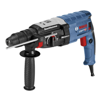
| Impact Energy | 3.2 J |
|---|---|
| Impact Rate at Rated Speed | 0 - 4000 bpm |
| Rated Speed | 0 - 900 rpm |
| Weight | 3.1 kg |
| Tool Dimensions (Height) | 216 mm |
| Tool Holder | SDS-plus |
| Drilling Diameter in Concrete with Hammer Drill Bits | 4 - 28 mm |
| Optimal Drilling Diameter in Concrete with Hammer Drill Bits | 8 - 16 mm |
| Drilling Diameter in Concrete with Core Cutters | 68 mm |
| Drilling Diameter in Masonry with Core Cutters | 68 mm |
| Drilling Diameter in Steel | 13 mm |
| Drilling Diameter in Wood | 30 mm |
| Power Source | Corded Electric |
| Vibration Level | 11.0 m/s² |



 Loading...