12 | English
1 609 92A 08V | (27.5.13) Bosch Power Tools
Technical Data
Assembly
Avoid unintentional starting of the machine. During as-
sembly and for all work on the machine, the power plug
must not be connected to the mains supply.
Delivery Scope
Carefully remove all parts included in the delivery from their
packaging.
Remove all packaging material from the machine and the ac-
cessories provided.
Before starting the operation of the machine for the first time,
check if all parts listed below have been supplied:
– Metal cutting saw with mounted saw blade
– Allen key/Phillips screwdriver 12
Note: Check the power tool for possible damage.
Before further use of the machine, check that all protective
devices are fully functional. Any lightly damaged parts must
be carefully checked to ensure flawless operation of the tool.
All parts must be properly mounted and all conditions fulfilled
that ensure faultless operation.
Damaged protective devices and parts must be immediately
replaced by an authorised service centre.
Stationary or Flexible Mounting
To ensure safe handling, the machine must be mounted
on a level and stable surface (e. g., workbench) prior to
using.
Mounting to a Working Surface (see figure A)
– Fasten the power tool with suitable screw fasteners to the
working surface. The mounting holes 23 serve for this pur-
pose.
Flexible Mounting (not recommended!)
If, in exceptional circumstances, it is not possible to securely
mount the power tool on a work surface, you can improvise by
placing the feet of the saw-table 25 on an appropriate base
(e.g. work bench, flat ground, etc.), without screwing down
the power tool.
Changing the Saw Blade (see figures B1–B4)
Before any work on the machine itself, pull the mains
plug.
Actuate the spindle lock 3 only when the tool spindle is
stopped. Otherwise, the machine can become damaged.
When mounting the saw blade, wear protective gloves.
Danger of injury when touching the saw blade.
Use only saw blades whose maximum permitted speed is
higher than the no-load speed of the power tool.
Use only saw blades that correspond with the characteristic
data given in these operation instructions and that are tested
and marked in accordance with EN 847-1.
Use only saw blades recommended by the tool manufacturer,
and suitable for sawing the materials to be cut.
Removing the Saw Blade
– Bring the power tool into the working position. (see “Re-
leasing the Machine (Working Position)”, page 13)
– Loosen the fastening screw 26 (approx. 2 turns) with the
Phillips screwdriver 12.
Do not completely unscrew the screw.
– Loosen the fastening screw 27 (approx. 6 turns) with the
Phillips screwdriver 12.
Do not completely unscrew the screw.
– Push the locking lever 1 and swing the retracting blade
guard 4 upwards to the stop.
– Then pull back the retracting guard blade 4 and the cover
plate 21 from the fastening screw 27 until the retracting
guard blade is held by the guide bolt 28 in the bracket 22.
– Turn the Allen screw 29 with the Allen key 12 provided
while at the same time pressing the spindle lock 3 until it
engages.
– Keep the spindle lock 3 pressed and unscrew the Allen
screw 29 in anticlockwise direction.
– Remove the clamping flange 30.
– Remove the saw blade 31.
Mounting the Saw Blade
If required, clean all parts to be mounted prior to assembly.
– Place the new saw blade onto the interior clamping flange
32.
When mounting the saw blade, pay attention that the
cutting direction of the teeth (arrow direction on the
saw blade) corresponds with the direction of the arrow
on the blade guard!
– Put on the clamping flange 30 and the screw 29.
Press the spindle lock 3 until it engages and tighten the
screw, turning in a clockwise direction.
– Loosen the spindle lock 3 again. If necessary, pull the knob
by hand all the way up.
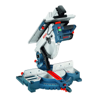
Metal Cutting Saw GCD 12 JL
Article number
3 601 M28 ...
... 0.. ... 060
Rated power input
W 2000 1650
No-load speed
min
-1
1500 1500
Soft starting
Laser type
nm
mW
650
< 0.39
650
< 0.39
Laser class
1M 1M
Weight according to
EPTA-Procedure 01/2003
kg 20 20
Protection class
/II /II
Permissible workpiece dimensions (maximal/minimal) see page 13.
The values given are valid for a nominal voltage [U] of 230 V. For differ-
ent voltages and models for specific countries, these values can vary.
Dimension of suitable saw blades
Saw blade diameter mm 305
Blade body thickness
mm 1.8–2.5
Mounting hole diameter
mm 25.4
OBJ_BUCH-1939-001.book Page 12 Monday, May 27, 2013 2:14 PM

 Loading...