16 | English
1 609 92A 14W | (21.1.15) Bosch Power Tools
28 Set of screw clamps*
29 Guide rail*
30 Connection piece*
31 Vacuum hose*
32 Cutting mark, 0°
33 Cutting mark, 45°
34 Plastic insert for base plate
35 Knurled screws for play adjustment of guide groove
*Accessories shown or described are not part of the standard de-
livery scope of the product. A complete overview of accessories
can be found in our accessories program.
Technical Data
Noise/Vibration Information
Sound emission values determined according to
EN 60745-2-5.
Typically the A-weighted noise levels of the product are:
Sound pressure level 92 dB(A); Sound power level
103 dB(A). Uncertainty K =3 dB.
Wear hearing protection!
Vibration total values a
h
(triax vector sum) and uncertainty K
determined according to EN 60745:
Cutting wood: a
h
<2.5 m/s
2
, K=1.5 m/s
2
,
Cutting metal: a
h
<2.5 m/s
2
, K=1.5 m/s
2
.
The vibration level given in this information sheet has been
measured in accordance with a standardised test given in
EN 60745 and may be used to compare one tool with anoth-
er. It may be used for a preliminary assessment of exposure.
The declared vibration emission level represents the main ap-
plications of the tool. However if the tool is used for different
applications, with different accessories or insertion tools or is
poorly maintained, the vibration emission may differ. This
may significantly increase the exposure level over the total
working period.
An estimation of the level of exposure to vibration should also
take into account the times when the tool is switched off or
when it is running but not actually doing the job. This may sig-
nificantly reduce the exposure level over the total working
period.
Identify additional safety measures to protect the operator
from the effects of vibration such as: maintain the tool and the
accessories, keep the hands warm, organisation of work pat-
terns.
Declaration of Conformity
We declare under our sole responsibility that the product de-
scribed under “Technical Data” is in conformity with all rele-
vant provisions of the directives 2011/65/EU,
2004/108/EC, 2006/42/EC including their amendments
and complies with the following standards: EN 60745-1,
EN 60745-2-5.
Technical file (2006/42/EC) at:
Robert Bosch GmbH, PT/ETM9,
70764 Leinfelden-Echterdingen, GERMANY
Robert Bosch GmbH, Power Tools Division
70764 Leinfelden-Echterdingen, GERMANY
Leinfelden, 21.01.2015
Assembly
Mounting/Replacing the Saw Blade
Before any work on the machine itself, pull the mains
plug.
When mounting the saw blade, wear protective gloves.
Danger of injury when touching the saw blade.
Only use saw blades that correspond with the charac-
teristic data given in the operating instructions.
Do not under any circumstances use grinding discs as
the cutting tool.
Selecting a Saw Blade
An overview of recommended saw blades can be found at the
end of this manual.
Removal of the Saw Blade (see figure A)
Adjust the maximal cutting depth, see section “Adjusting the
Cutting Depth”.
For changing the cutting tool, it is best to place the machine
on the face side of the motor housing.
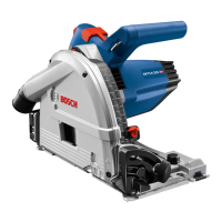
Circular Saw GKT 55 GCE
Article number
3 601 F75 0..
Rated power input
W1400
No-load speed
min
-1
3600 – 6250
Rotational speed under load, max.
min
-1
5900
Cutting depth, max.
–for 0° bevel angle
–for 45° bevel angle
mm
mm
57
42
Spindle lock
Speed preselection
Constant electronic control
Reduced starting current
Base plate dimensions
mm 154 x 305
Saw blade diameter, max.
mm 165
Saw blade diameter, min.
mm 160
Blade thickness, max.
mm 1.8
Tooth thickness/setting, max.
mm 2.6
Tooth thickness/setting, min.
mm 1.8
Mounting bore
mm 20
Weight according to
EPTA-Procedure 01/2003
kg 4.7
Protection class
/ II
The values given are valid for a nominal voltage [U] of 230 V. For differ-
ent voltages and models for specific countries, these values can vary.
Henk Becker
Executive Vice President
Engineering
Helmut Heinzelmann
Head of Product Certification
PT/ETM9
OBJ_BUCH-1471-002.book Page 16 Wednesday, January 21, 2015 1:35 PM
 Loading...