8
Technical Characteristics and Dimensions
6 720 608 992 (2018/01)
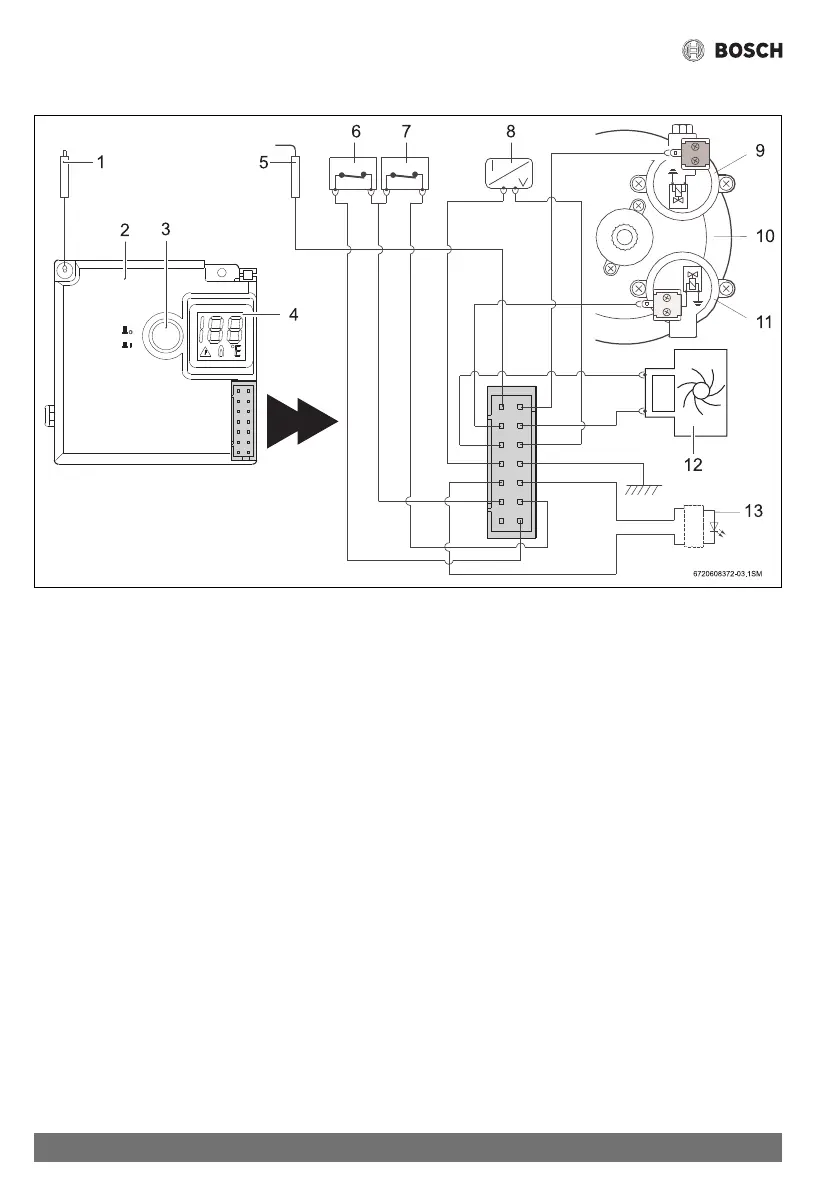
2.7 Electrical diagram
Fig. 3 Electrical diagram
[1] Ignition electrode
[2] Ignition unit
[3] Switch/LED - Low water pressure indicator
[4] Digital display
[5] Ionisation probe
[6] Flue gas safety device
[7] Overtemperature switch
[8] Temperature sensor
[9] Pilot solenoid (Normally Closed)
[10] Diaphragm valve
[11] Main Solenoid (Normally Open)
[12] Hydrogenerator
[13] LED - Burner status check
2.8 Function
This gas heater is equipped with automatic electronic ignition
to simplify operation.
▶ To activate, just turn on the switch (Fig. 8).
After this, automatic ignition occurs whenever a hot water tap
is opened. First, the pilot burner is lit and approximately four
seconds later the main burner ignites. The pilot burner flame is
extinguished after the main burner lights.
This is a way of saving a great amount of energy as the pilot
burner only operates for the minimum necessary time to ignite
the main burner.
 Loading...