6 720 608 782
50
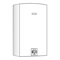
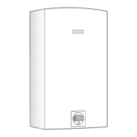
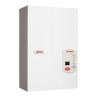
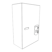
Interior components diagram and parts list
12.2.3 Group 3
Fig. 67 Components Diagram
15
14
1
3
4
6
7
8
2
12
9
10
11
13
16
17
5
6720902975.AA JF
Item Description Reference
1 Main burner 8 708 120 642
2 Burner gasket 8 704 701 087
3 Primary fan 8 707 204 071
4 Backflow temperature sensor 8 707 206 459
5 Washer 8 704 701 097
6 Fan mount nut 2 915 011 006
7 Secondary fan 8 707 204 072
8 Screw 8 703 403 012
9 Gas / Air Mixer 8 705 700 170
Table 23
10 Air duct O-ring 8 700 205 149
11 Venturi 8 700 306 226
12 O-ring 8 700 205 224
13 Mixer / Fan gasket 8 704 701 059
14 Screw 2 910 642 150
15 Plate gasket 8 701 004 049
16 Air supply duct 8 705 700 155
17 Screw 2 910 952 122
Item Description Reference
Table 23

 Loading...

