6 720 819 528 (2016/02)Therm 4000 S
Product details | 7
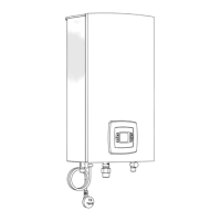
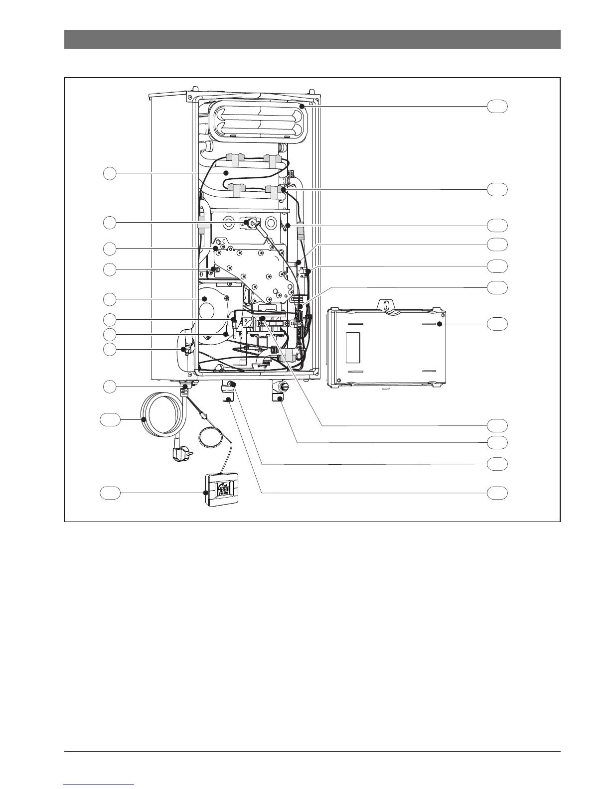
2.8 Appliance layout
Fig. 2
[1] Combustion chamber
[2] Monitoring electrode
[3] Burner
[4] Air pressure head in the box
[5] Fan
[6] Air temperature sensor of the box
[7] Thermofuse
[8] Hot water temperature sensor
[9] Water outlet
[10] Connecting lead with plug
[11] Remote control
[12] Combustion gas collector
[13] Anti freeze kit
[14] Ignition electrode
[15] Gas pressure head in the burner
[16] Cold water temperature sensor
[17] Water flow sensor
[18] Control box
[19] Gas valve
[20] Water inlet
[21] Incoming gas pressure head
[22] Gas
 Loading...