Do you have a question about the Bosch HBL54x0UC and is the answer not in the manual?
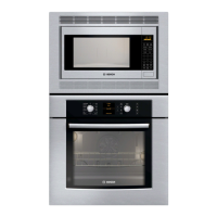
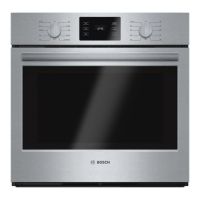
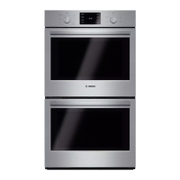
Lists the Bosch 300, 500, and 800 series built-in wall oven models.
Details the features and options available across different Bosch oven models.
Describes how heating elements cycle during preheating for various cavity types.
Illustrates the sequence of events during oven preheating modes.
Explains the operation and shut-off behavior of the oven's cooling fans.
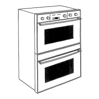
Lists components accessible from the front of the oven.
Lists components accessible from the top of the oven after sliding it out.
Lists components accessible from the rear of the oven after removing the back panel.
Discusses door types and specifics for Bosch ovens.
Provides instructions for safely removing and reinstalling oven doors.
Details the operation and replacement of oven cavity lights.
Instructions for replacing halogen and incandescent appliance bulbs.
Step-by-step guide for replacing vertical-style halogen side lamps.
Step-by-step guide for replacing horizontal-style halogen side lamps.
Instructions for replacing ceiling lamps and incandescent cavity lamps.
Explains the function and reset procedure for the High Temperature Cutout.
Describes the convection fan and ring element configurations and their use.
Details how to test the temperature sensor and its resistance readings.
Instructions for adjusting oven temperature settings via offsets.
Information on the recessed broil element, including testing resistance.
Overview of the B1, B2, and B3 user interface variations.
Step-by-step instructions for removing the user interface assembly.
Information on accessing and servicing the PC control module.
Details the power supply module providing DC voltage to control and interface modules.
Explains the function and testing of halogen light transformers used in cavities.
Describes the convection fan motor, its power, and testing procedures.
Information regarding the upper oven bake element, including removal.
Step-by-step instructions for removing the upper oven bake element.
Instructions for reinstalling the upper oven bake element.
Details the upper oven cooling fan motor, its terminals, and Hall effect sensor.
A table listing error codes, their causes, and actions for troubleshooting.
Instructions for entering service mode and setting option codes for oven configuration.
Steps to enter service mode for HBL3/HBN3 models.
Steps to enter service mode for HBL5/HBN5 models.
Steps to enter service mode for HBL8 models.
A table listing model-specific option codes for oven configuration.
A diagram to guide troubleshooting by analyzing unit behaviors and statuses.
Provides a step-by-step fault tree analysis for various oven operational failures.
Troubleshooting guide for when oven keys are not functional.
Troubleshooting steps for when the oven does not heat properly.
Troubleshooting steps for communication loss errors between components.
Troubleshooting steps for when the oven does not maintain heat.
Details testing procedures for various oven components using pin headers or open circuits.
A key that defines the color coding for wires used in oven wiring diagrams.
Illustrates strip diagrams for Bosch upper and lower oven elements.
Information on how to access additional documents and resources via QuickFinder.
Contact information for Bosch technical support.