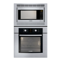
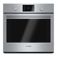
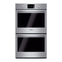
Service Manual for Bosch Built-in Wall Ovens
7.3 Testing
Test with wire harness off at pin header or with circuits open.
Plug Pins Operates Explanation
X102
and
X103
4, 5
2, 4
Upper oven
double line break
relay coil
No fail code. If double line break relay
does not close, L2 (120 volts) will not
reach upper oven bake, broil,
convection elements.
X105 7 Upper door latch
motor
Will accept all modes except self-
clean. When oven set to self-clean,
display will be on constantly, doors
will not lock and self-clean will not
start. E106 will appear.
X105 6 Upper oven
convection motor
No fail code. Lower oven convection
motor will not work.
X105 1 Rotisserie motor No failure code. Rotisserie will not
rotate.
X106 1 (common),
6, 7
Upper oven door
latch
If latch position is not detected during
normal operation, E124/126 will be
displayed.
X107 4, 5 Upper oven
sensor
Controls function normal. When
sensor opens, E101 code will appear.
If sensor shorts, E104 will appear.
Cooling fan is on constantly.
X107
X207
1, 2, 3
1,4,5
Cooling fan
motors
Will accept modes. In ~45 seconds,
E118 will appear in upper oven
display or E218 will appear in lower
oven display when hall sensor does
not detect fan rotation.
X202
and
X203
1, 2
3, 5
Lower oven
double line break
relay coil
No fail code. If double line break relay
does not close, L2 (120 volts) will not
reach lower oven bake, broil,
convection elements.
X205 6 Lower door latch
motor
Will accept all modes except self-
clean. When oven set to self-clean,
display will be on constantly, doors
will not lock and self-clean will not
start. E206 will appear.
X205 1 Lower oven
convection motor
No fail code. Lower oven convection
motor will not work. Relay will snap
closed.
Plug Pins Operates Explanation
X206 1 (common),
6, 7
Lower oven door
latch
If latch position is not detected during
normal operation, E224/226 will be
displayed.
X207 3, 6 Lower oven
sensor
Control functions normal. When
sensor opens, E201 code will appear.
If sensor shorts, E204 will appear.
Cooling fan is on constantly.
X2 Sends display
signal to display
Glass control panel is completely
dead. 3-position connector
(ground/voltage/data line) should
measure 9.6 VDC.
X2 Sends
communication
signals to display
If no communication between
electronic modules, E005 will display.
Connector positions 1-2 should
measure ~5 VDC.
8 WIRING DIAGRAMS AND SCHEMATICS
The wire color key (Table 10) and element strip diagrams (Figures 23-
24) are shown below. For schematics, please refer to the Built-in
Oven Service Guide (Wiring Diagram) which can be found on
QuickFinder or in the upper oven plenum, near the control module.
8.1 Wire Color Key
BK BN
Black Brown
BU
Blue
GN OR
Green Orange
RD
Red
VT WH
Violet White
YE
Yellow
BN/WH BU/WH
Brown/White Blue/White
OR/BK
Orange/Black
VT/WH YE/BK
Violet/White Yellow/Black
Table 9 Troubleshooting
Table 10 Wire color key
Page 33 of 36
 Loading...