58300000202443_ARA_EN_C JANUARY 2018 Service Manual for Bosch 800 Series Built-in Wall Ovens
Page 14 of 43
Copyright by BSH Home Appliances Corporation 1901 Main St ▪ Suite 600 ▪ Irvine, CA 92614 800 944-2904
This material is intended for the sole use of BSH authorized persons and may contain confidential and proprietary information. Any unauthorized review, use, copying, disclosure, or distribution in any format is prohibited.
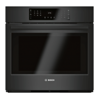
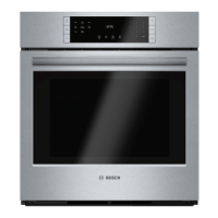
5.4.1 Top Access: Non-combination Models
To reach the service panel, remove the screws securing the side trim
to the cabinetry, and slide the oven out of the cutout ~8-9 inches.
For unrestricted access to the top front plenum area, remove the
screws securing the side trim pieces to the cabinetry, then slide the
oven out of the cutout approximately ~16 inches, and remove the top
front housing cover completely.
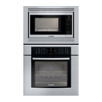
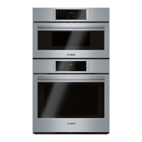
5.4.2 Top Access: Combination Models
To reach the service panel on an HBL8742UCC,
HBL8752UCC or HBL87M52UCC oven,
follow the steps below...
1. Remove the screws securing the right
and left side trim pieces to the
cabinetry.
2. Carefully slide the combination
oven out of the cutout ~8-9 inches.
3. Remove the locking screw from the
right and left service slides (see Figure
6).
4. Carefully slide the microwave or steam
oven to the rear ~7 inches; the service
access panel will be accessible.
Note that the length of the conduit/feeder wires which connect the
microwave to the oven beneath it are ~5’ long. If there is a work table
nearby, it may not be necessary to disconnect the feeder wires from
the terminal block located in the oven-mounted junction box on the top
of the oven housing.
When servicing the standard wall oven component of an
HBL8742UCC, HBL8752UC, or HBL87M52UC combination oven,
only the top front service access panel will be accessible without
removing the microwave oven.
If additional access to the top area of the oven is required, the
microwave oven component must be removed. To safely remove
and reinstall the microwave oven, two people are required.
 Loading...