EasyManua.ls Logo

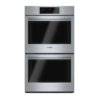
Bosch HBN8651UC User Manual

Bosch HBN8651UC
43 pages
To Next Page IconTo Next Page
Page #1 background imageLoading...
Page #1 background image
S
ERVICE
M
ANUAL
for
800 Series
Built-in Wall Ovens
HBL8442UC HBL8752UCC*
HBL8451UC HBL87M52UCC*
HBL8461UC HBL8742UCC*
HBL8642UC
HBL8651UC HBN8451UC
HBL8661UC HBN8651UC
This manual contains information that is necessary for
servicing the following Bosch electric built-in wall ovens:
HBL8442UC, HBL8451UC, HBL8461UC, HBL8642UC,
HBL8651UC, HBL8661UC, HBL8742UC
HBL8752UCC, HBL87M52UCC, HBL8742UCC
HBN8451UC, HBN8651UC
This manual is designed to be used by qualified service
personnel only. Due to the complexity and the risk of
high-voltage electrical shock, Bosch does not recommend
that customers service their own units.
This material is intended for the sole use of BSH
authorized persons and may contain confidential and
proprietary information. Any unauthorized review, use,
copying, disclosure, or distribution in any format is
prohibited.
*HBL8752UCC is the traditional wall oven component of
the HBL8752UC combination oven (set), which also
includes the HMC80252UC Speed microwave oven.
**HBL87M52UCC is the traditional wall oven component
of the HBL87M52UC combination oven (set), which also
includes the HMB50152UC Solo microwave oven.
**HBL8742UCC is the traditional wall oven component of
the HBL8742UC combination oven (set), which also
includes the HMC80242UC Speed microwave oven.

Table of Contents

Other manuals for Bosch HBN8651UC

Questions and Answers:

Bosch HBN8651UC Specifications

General IconGeneral
Styledouble wall oven
Colorstainless steel
Main Oven Capacity3.9 cubic feet
Extra Oven Capacity3.9 cubic feet
Main Oven Convectionfalse, true convection
Extra Oven Convectionyes
Number of Main Oven Rack Positions6
Number of Extra Oven Rack Positions6
Number of Main Oven Racks2
Number of Extra Oven Racks3
Control Typetouchpad
Interior Lightyes
Child Lockfalse, true
Kitchen Timeryes
Smart Homeno
Wi-Finone
Power Consumption2400 watts
Weight and Dimensions IconWeight and Dimensions
Voltage230 volts
Current40 amperes
Depth24 1/2 inches
Height52 1/16 inches
Width27 inches
Net Weight243 pounds

Summary

Symbols Used in Manual

Important Safety Information

Safety Before Servicing

Safety precautions and procedures to follow before performing service on the appliance.

General Oven Information

Functional/Technical Changes Recap

Summary of functional and technical updates made to the 800 Series built-in wall ovens.

Oven Models Overview

Overview of the Bosch 800 Series built-in wall oven model structure and available configurations.

Rating Label Identification

Information on the location and importance of the model and FD number rating label.

Product Warranty Details

Details on the product warranty period and Bosch's liability for repairs performed by non-authorized servicers.

Oven Operation and Features

Operating Range by Cooking Mode

Table detailing min/max/default operating temperatures for various cooking modes across 800 Series models.

Heating Element Descriptions

Description of broil, bake, and Euro-convection ring elements used in the 800 Series ovens.

Elements Used by Cooking Mode

Table showing which heating elements are utilized for each specific cooking mode.

Element Duty Cycles

Details on element start/duration cycles during preheat and regulate phases for different modes.

Setting Temperature Offsets

Instructions for adjusting oven temperature settings to compensate for under or over-cooking reports.

Self-clean Operation

Information regarding the self-clean function and its effect on double ovens.

Cooling Fan Operation

Explanation of the cooling fan's operation, speed variations, and error code triggers.

Component Accessibility

Serviceable from the Front

List of oven components accessible for servicing from the front of the appliance.

Serviceable from the Side

List of components serviced after pulling unit away from wall and removing side panels.

Serviceable from the Rear

List of components serviced from the rear of the oven after removing back housing panel.

Serviceable from the Top

Access to top front plenum area via service panel, including control module accessibility.

Top Access Procedures

Top Access: Non-combination Models

Procedure for accessing the top front plenum area on non-combination models.

Top Access: Combination Models

Steps to access service panel on combination models, including microwave oven removal.

Service and Repair: Doors

Door Assembly Overview

Serviceable parts for soft-close door assembly: handle, glass, hinges.

Removing and Reinstalling Door

Step-by-step instructions for safely removing and reinstalling the oven door.

Replacing Oven Hinges

Procedure for replacing soft-close hinges, emphasizing replacement in pairs.

Replacing 2-Pane Glass Pack

Steps for accessing and replacing oven's 2-pane glass pack, with safety precautions.

Service and Repair: Latches and Cutouts

Door Latch/Motor Assembly

Description of motorized door latch mechanism, its switches, and service as an assembly.

Replacing Latch/Motor Assembly

Instructions for removing and installing the door latch/motor assembly.

Oven High Temperature Cutout (HTC)

Explanation of resettable HTC function in detecting and preventing over-temperature conditions.

Resetting and Replacing HTC

Instructions for resetting a tripped HTC and detailed steps for replacing the HTC component.

Service and Repair: Control Panel and Lights

Control Panel Components

Overview of control panel components: front panel assembly and touch control module (TCM).

Replacing Front Panel Assembly

Procedure for removing and replacing the entire front panel assembly.

Replacing Display Module

Steps for removing and installing the display module from the control panel carrier.

Cavity Lights

Information on bulb types for cavity lights in 27"/30" ovens and their operation.

Replacing Oven Lamp

Instructions for replacing the oven's interior light bulb, including safety precautions.

Service and Repair: Heating Components

Convection Fan, Ring Element, Motor

Description of convection fan, ring element, and motor in Euro-convection cavities and their functions.

Replacing Convection Fan Blade

Step-by-step guide for removing and installing the convection fan blade.

Replacing Ring Element

Procedure for replacing convection ring element, noting potential short wire issues.

Replacing Convection Fan Motor

Instructions for removing and installing the convection fan motor.

Broil Element

Description of 240V broil element, its reflector, and testing methods.

Replacing Broil Element

Procedure for removing and replacing broil element, including front and rear access.

Bake Element

Information about 240V bake element, its location, and testing procedures.

Replacing Bake Element

Guide for accessing and replacing bake element, typically from the rear.

Service and Repair: Sensors and Modules

Temperature Sensor

Details on PT1000 temperature sensor, its location, and normal resistance readings.

Control Module and Daughter Board

Explanation of control module function and accessibility of control modules and daughter boards.

Replacing Control Module or Daughter Board

Instructions for removing and installing control module or daughter board, including harness disconnection.

Cooling Fan

Description of cooling fan assembly, variable speed operation, and HTC component.

Replacing Cooling Fan

Procedure for removing and installing cooling fan, accessing from rear of unit.

Service and Repair: Hinge Receivers

Hinge Receivers

Information on replacing hinge receivers, requiring oven pull-out for side panel access.

Replacing Hinge Receivers

Detailed steps for removing and installing oven hinge receivers.

Troubleshooting Oven Issues

Oven Error Codes

Overview of error codes, their descriptions, causes, and suggested actions for troubleshooting oven issues.

Accessing Service Mode

Guide to accessing and navigating the Service Mode menu for diagnostics and settings.

Setting Option Code

Instructions for manually programming or changing unit's option code within Service Mode.

Displaying Error Memory

Procedure for viewing logged error codes and their counts from Service Mode.

Testing Relays

Guide to performing relay tests within Service Mode to check component functionality.

Testing Front Panel

Procedure for testing control inputs and buttons on front panel using Service Mode.

Fault Trees and Schematics

Fault Trees for Troubleshooting

Flowcharts to guide troubleshooting efforts for common oven operational failures.

Wiring Diagrams and Schematics

Reference for wire color key and element strip diagrams for oven electrical systems.

Wire Color Key

Key identifying wire colors used in oven's electrical system and their terminal connections.

Strip Diagrams

Visual representation of element connections and wiring paths for different oven cavities.

Additional References

QuickFinder Resources

Accessing additional service documents, exploded views, and parts lists via QuickFinder.

Technical Support Contact

Contact info for authorized servicers to get assistance from Bosch Technical Support.

Related product manuals