EasyManua.ls Logo

Bosch HBN8451UC User Manual

Bosch HBN8451UC
43 pages
To Next Page IconTo Next Page
Page #1 background imageLoading...
Page #1 background image
S
ERVICE
M
ANUAL
for
800 Series
Built-in Wall Ovens
HBL8442UC HBL8752UCC*
HBL8451UC HBL87M52UCC*
HBL8461UC HBL8742UCC*
HBL8642UC
HBL8651UC HBN8451UC
HBL8661UC HBN8651UC
This manual contains information that is necessary for
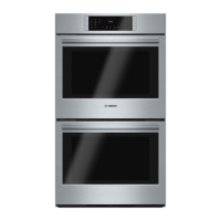
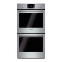
servicing the following Bosch electric built-in wall ovens:
HBL8442UC, HBL8451UC, HBL8461UC, HBL8642UC,
HBL8651UC, HBL8661UC, HBL8742UC
HBL8752UCC, HBL87M52UCC, HBL8742UCC
HBN8451UC, HBN8651UC
This manual is designed to be used by qualified service
personnel only. Due to the complexity and the risk of
high-voltage electrical shock, Bosch does not recommend
that customers service their own units.
This material is intended for the sole use of BSH
authorized persons and may contain confidential and
proprietary information. Any unauthorized review, use,
copying, disclosure, or distribution in any format is
prohibited.
*HBL8752UCC is the traditional wall oven component of
the HBL8752UC combination oven (set), which also
includes the HMC80252UC Speed microwave oven.
**HBL87M52UCC is the traditional wall oven component
of the HBL87M52UC combination oven (set), which also
includes the HMB50152UC Solo microwave oven.
**HBL8742UCC is the traditional wall oven component of
the HBL8742UC combination oven (set), which also
includes the HMC80242UC Speed microwave oven.

Table of Contents

Other manuals for Bosch HBN8451UC

Questions and Answers:

Bosch HBN8451UC Specifications

General IconGeneral
Oven sizeMedium
Oven typeElectric
Self-cleaningYes
Number of ovens1
Convection power2000 W
Total oven power3800 W
Auto programs quantity12
Total oven(s) interior capacity110 L
Maximum temperature (convection)230 °C
Lamps quantity2 lamp(s)
Door hingedown
Cord length1.27 m
Control typeButtons, Sensor
CertificationCSA
Product colorStainless steel
Control positionFront
Interior materialAluminum
Appliance placementBuilt-in
Clock typeElectronic
Timer typeDigital
Current30 A
Connected load5000 W
AC input voltage208-240 V
AC input frequency60 Hz
Energy efficiency class-
Energy consumption (forced convection)- kWh
Package depth800 mm
Package width870 mm
Package weight74000 g
Weight and Dimensions IconWeight and Dimensions
Depth600 mm
Width680 mm
Height740 mm
Weight67130 g

Summary

Symbols Used in this Manual

Important Safety Information

Safety Before Servicing the Appliance

Precautions and safety measures before starting service work on the appliance.

General Oven Information

Recap of Functional/Technical Changes

Summary of key functional and technical updates for the 800 series ovens.

Bosch 800 Series Oven Models

Details the model number structure and lists available 800 Series oven models.

Oven Rating Label

Explains the location and importance of the model and FD number rating label.

Product Warranty Information

Outlines the product warranty period and conditions for repairs.

Oven Operation

Allowable Operating Range by Cooking Mode

Lists minimum, maximum, and default temperature ranges for various cooking modes.

Heating Elements Overview

Describes the types of heating elements used in the ovens and their wattage.

Elements Used by Cooking Mode

Details which heating elements are used for each specific cooking mode.

Element Duty Cycles

Explains the start and duration cycles for heating elements during preheat and regulate phases.

Setting Temperature Offsets

Guides on how to adjust oven temperature settings for consistent cooking results.

Self-clean Cycle Notes

Notes behavior of double ovens during self-clean cycle.

Cooling Fan Functionality

Explains the function and operation of the cooling fan during different oven modes.

Component Accessibility

Serviceable from the Front

Lists components that can be accessed and serviced from the front of the oven.

Serviceable from the Side

Lists components accessible for servicing after removing side panels.

Serviceable from the Rear

Lists components accessible for servicing after removing the rear housing panel.

Serviceable from the Top

Describes access to components via the top front housing cover.

Top Access: Non-combination Models

Details how to access the service panel on non-combination models.

Top Access: Combination Models

Provides steps for accessing the service panel on combination oven models.

Service and Repair Procedures

Oven Doors

Lists serviceable parts of the oven door assembly.

Removing and Reinstalling the Oven Door

Step-by-step instructions for safely removing and reinstalling the oven door.

Replacing Oven Hinges

Guides on replacing soft-close hinges, noting they must be replaced in pairs.

Replacing the 2-Pane Glass Pack

Instructions for accessing and replacing the oven's 2-pane glass pack.

Door Latch/Motor Assembly

Details the motorized door latch mechanism and its components.

Replacing the Latch/Motor Assembly

Step-by-step instructions for replacing the door latch/motor assembly.

Oven High Temperature Cutout (HTC)

Explains the function of the resettable HTC and its role in over-temperature protection.

Resetting and Replacing the HTC

Provides procedures for resetting and replacing the High Temperature Cutout (HTC).

Control Panel Components

Describes the components of the oven's control panel assembly.

Replacing the Front Panel Assembly

Instructions for removing and replacing the entire front panel assembly.

Replacing the Display Module

Steps for removing and installing the display module from the control panel carrier.

Cavity Lights Information

Information on the types of bulbs used for oven cavity lighting and their operation.

Replacing the Oven Lamp

Procedure for replacing the oven cavity light bulb.

Convection Fan, Ring Element, and Motor

Overview of convection fan, ring element, and motor components in the oven.

Replacing the Convection Fan Blade

Steps for removing and installing a new convection fan blade.

Replacing the Ring Element

Instructions for replacing the convection ring element.

Replacing the Convection Fan Motor

Procedure for removing and installing the convection fan motor.

Broil Element Details

Details the broil element, its function, and testing.

Replacing the Broil Element

Step-by-step guide to replacing the broil element.

Bake Element Information

Information on the bake element and testing.

Replacing the Bake Element

Instructions for replacing the bake element.

Temperature Sensor

Describes the PT1000 temperature sensor and its resistance readings.

Control Module and Daughter Board

Explains the function of the control module and daughter board in oven operation.

Replacing Control Module or Daughter Board

Detailed instructions for replacing the control module or daughter board.

Cooling Fan System

Information on the cooling fan and testing.

Replacing the Cooling Fan

Steps for replacing the cooling fan.

Hinge Receivers

Replacing the Hinge Receivers

Instructions for replacing the hinge receivers.

Troubleshooting Oven Issues

Understanding Error Codes

Explains the location of error code information and how error codes are designated.

Service Mode Overview

Overview of Service Mode access and available diagnostic functions.

Accessing Service Mode

Step-by-step guide on how to enter the oven's Service Mode.

Setting the Option Code

Instructions for manually programming the oven's option code in Service Mode.

Displaying Error Memory

How to view logged error codes and their counts from the oven's memory.

Testing Oven Relays

Procedure for testing oven relays within Service Mode.

Testing the Front Panel

Guide for testing all control inputs on the oven's front panel.

Fault Trees for Troubleshooting

OVEN DISPLAY DEAD Troubleshooting

Troubleshooting guide for ovens with a dead display but responsive buttons.

Failure During Operation Troubleshooting

Troubleshooting guide for ovens that fail during operation after initial use.

OVEN DOES NOT HEAT Troubleshooting

Troubleshooting guide for ovens where heating elements are not operating.

Wiring Diagrams and Schematics

Wire Color Key

Key to understanding wire colors used in the oven's wiring diagrams.

Strip Diagrams

Visual representations of element connections and pathways within the oven.

Additional References

QuickFinder Document Guide

Guide to accessing additional service documents and exploded views via QuickFinder.

Bosch Technical Support

Contact information for Bosch Technical Support for authorized servicers.

Related product manuals