Constant Response Circuitry
The internal electronic feedback system
provides a "soft start", which will reduce
the stresses that occur from a high
torque start. The system also maintains
the selected speed under load for
maximum efficiency.
Blade Orbit Selector Lever
Maximum cutting efficiency can be
obtained by adjusting the blade orbit
selector lever to suit the material being
cut.
The following chart will help you
determine which setting to use for your
application. This chart is intended as a
guideline only, and test cuts in scrap
material should be performed first to
determine the best setting.
Setting O
Hard materials such as
metals or thin sheet
metals. This setting can
be used with knife
blades, grit edge blades,
rasp work and down
cutting blades.
Setting I
Soft materials where
cleaner cutting or
delicate scrolling work is
performed.
Setting II
Medium density
materials such as harder
woods or particle board.
Setting III
Soft materials such as
wood, plastics, etc. and
when fast cutting is
more important than a
clean cut.
Chip Blower
Your jig saw is equipped with a two
position chip blower to help keep the
cutting line clear of chips.
By adjusting the chip blower lever the
force of the discharge air may be altered
as follows;
BLOWER SWITCHED ON
For working with wood,
plastic and similar
materials that produce
large amounts of sawdust.
BLOWER SWITCHED OFF
For working with metals
and when cooling agents
are used, or with dust
collection accessory.
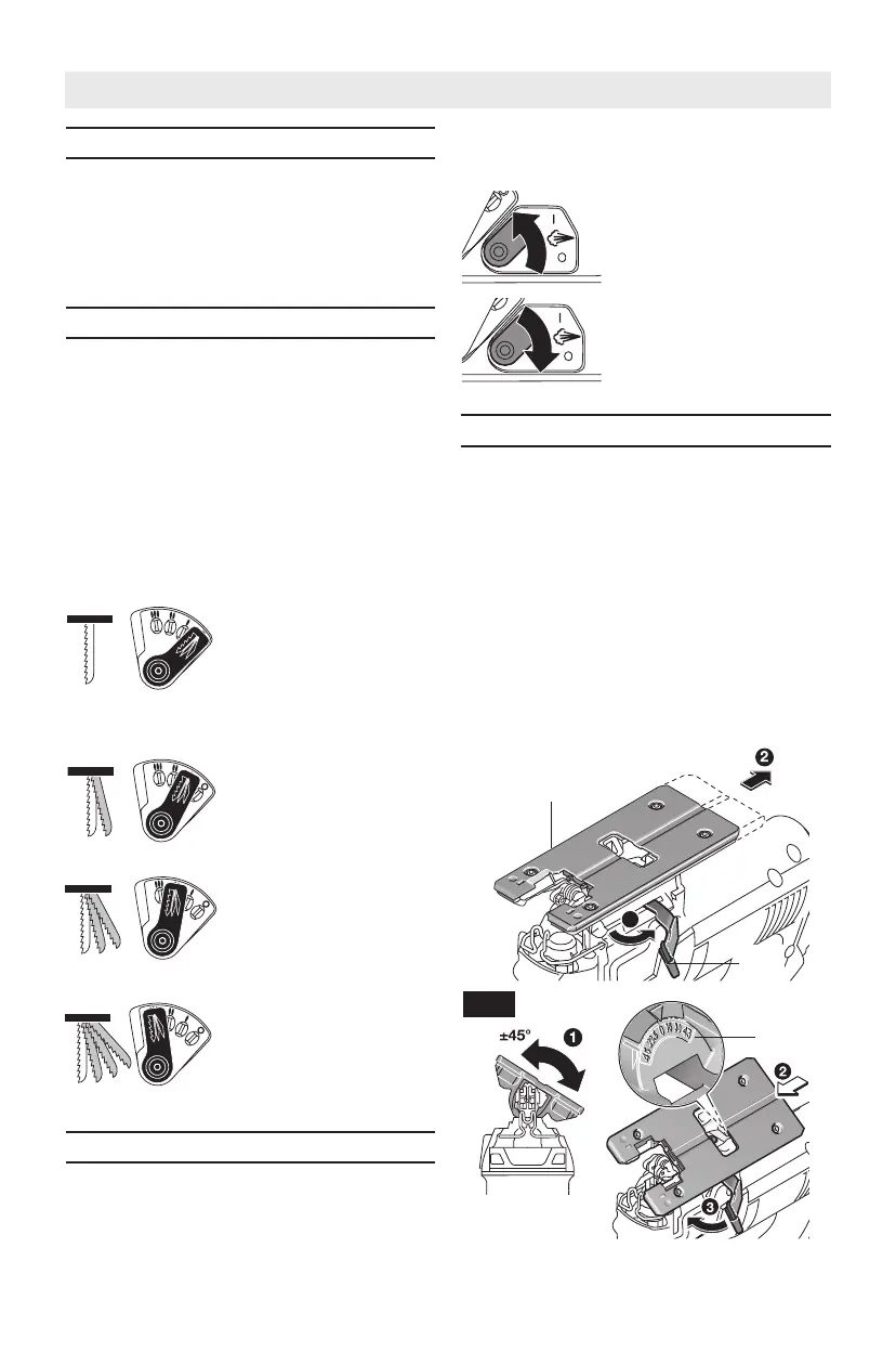
Footplate Angle Adjustment
The footplate may be tilted to allow
angle cuts up to 45° in either direction
(Fig. 8).
Note: before adjusting the footplate,
remove dust shroud and anti-splinter if
used.
Open the lock lever to unlock footplate.
Push and hold the footplate firmly
towards the back of tool as shown.
While holding the footplate backwards
tilt footplate to desired angle on bevel
scale, then release pressure on
footplate so it engages into detent at
desired angle (Fig. 8).
LOCK
LEVER
BEVEL
SCALE
FOOTPLATE
FIG. 8
-12-
Operating Instructions