Do you have a question about the Bosch KTS 570 and is the answer not in the manual?
| Connectivity | USB |
|---|---|
| Supported Protocols | ISO 9141-2, UDS |
| Power Supply | Vehicle battery via OBD-II connector or external power supply |
| Operating Voltage | 12 V / 24 V |
| Storage Temperature | -20°C to +70°C |
| Display | None (uses display of connected PC) |
| Compatibility | Bosch ESI[tronic] software, supports multiple vehicle brands |
| Functionality | Vehicle diagnostics, coding, programming, and guided functions |
Notes on copyright, liability, warranty, user group and contractor obligations, and safety instructions.
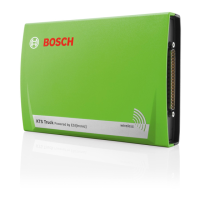
Explains Bluetooth, potential interference sources, and optimal placement for reliable connection.
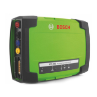
KTS modules are for controller diagnosis; functionality differences are shown in a table.
Lists PC/Laptop hardware with USB and compatible operating systems (WIN XP) needed for KTS modules.
Details required PC/Laptop hardware with USB interface and compatible Bosch products.
Lists all parts included in the KTS module delivery with their respective order numbers.
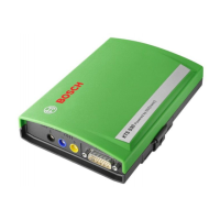
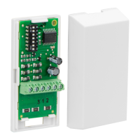
Explains the function of diagnosis and measurement terminals (CH1, CH2, GND, DIAG) on the system tester.
Details the meaning of LED A and LED B states for diagnosis and power status indication.
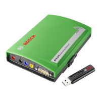
Explains the function of the Bluetooth USB adapter and handling precautions for connectivity.
Explains symbols for Bluetooth Manager and Bosch Bluetooth Device in the toolbar for status indication.
Illustrates the connection diagram for KTS modules to the vehicle and PC/Laptop.
Notes on powering KTS modules and vehicle supply during testing, especially when starting the motor.
Procedure for updating KTS module firmware via USB connection or Diagnostic Device Configuration (DDC).
Troubleshooting steps when diagnosis hardware is not detected by the control unit diagnosis software.
Troubleshooting steps for the 'No communication with the control unit' fault message.
Instructions for mounting the KTS module onto a Bosch trolley using provided screws.
Details on installing the required ESI[tronic] software for KTS modules on a PC/Laptop.
Steps to connect the KTS module to its power supply and the PC/Laptop via USB cable.
Guidelines for cleaning the KTS module housing using a soft cloth and neutral cleaning agent.
Lists replacement and wear parts that are received with the respective KTS module delivery.
Lists general properties like operating voltage, power consumption, dimensions, weight, and temperature.
Specifies measurement ranges, precision, and resolution for DC measurements on CH1 and CH2.
Specifies measurement ranges, precision, and resolution for AC and effective value measurements.
Specifies measurement ranges, precision, and input resistance for resistance measurements on CH1.