Do you have a question about the Bosch D9127U and is the answer not in the manual?
Instructions for safely removing the POPIT module cover using a screwdriver.
Procedure for detaching the Printed Circuit Board (PCB) from the POPIT module base.
Guidance on mounting the POPIT module base using supplied hardware.
Steps for re-inserting the POPIT module's PCB back into its base securely.
Details on setting DIP switches for POPIT module configuration.
The D9127 Series POPIT Modules, comprising the D9127T (with a magnetic tamper switch) and the D9127U (without a tamper switch), are designed to extend the capabilities of compatible control panels by expanding their initiating points beyond the standard on-board count. These modules are a key component for economical future system expansion, as they can be integrated anywhere along a two-wire data expansion loop.
The core function of the D9127 Series POPIT Modules is to provide point supervision and individual device addressing over a single pair of wires, effectively expanding the zone capacity of a control panel. This is achieved through proven technology that integrates these two critical functions. The modules act as an interface between sensors and the control panel, allowing the panel to monitor a greater number of points than its inherent capacity. This expansion capability is particularly useful in larger installations or when future growth is anticipated, as it avoids the need for more complex and costly wiring schemes.
The D9127T model includes a magnetic tamper switch, which adds an extra layer of security by detecting unauthorized attempts to open or remove the device. This feature is crucial in applications where physical security of the module itself is a concern, providing immediate notification to the control panel if tampering occurs. The D9127U model, without the tamper switch, offers a more streamlined and cost-effective solution for environments where physical tampering is less of a risk or where other tamper detection methods are already in place.
The modules communicate with the control panel via a two-wire data expansion loop. This loop is designed for simplicity and efficiency, allowing multiple POPIT modules to be connected in series, each adding its own set of supervised points. This daisy-chaining capability makes the system highly scalable and flexible, as modules can be added or removed as needed without significantly altering the existing wiring infrastructure. The data expansion loop also ensures reliable communication between the modules and the control panel, maintaining the integrity of the security system.
The D9127 Series POPIT Modules are designed for ease of installation and configuration, making them suitable for a wide range of applications. Their compact size allows them to be installed in various locations, including standard outlet boxes, above false ceilings, inside closets, or other accessible areas where they can be discreetly integrated into the building's infrastructure. This flexibility in placement helps maintain the aesthetic integrity of the environment while ensuring optimal sensor coverage.
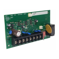
Wiring is facilitated by screw terminals, which provide reliable connections for both the data expansion loop and the supervised sensor loop. Screw terminals are known for their secure grip on wires, minimizing the risk of loose connections that could lead to intermittent faults or system failures. This robust connection method ensures long-term stability and performance of the security system. When using 12 AWG (0.1 mm) maximum wire, solid wire is recommended for optimal performance. If stranded wire is used, care must be taken to insert all strands into the terminal block to ensure a complete and secure connection.
Configuration of the POPIT modules involves setting DIP switches, which determine the module's address and other operational parameters. The DIP switch settings are crucial for proper communication with the control panel and for assigning unique identifiers to each module within the expansion loop. Detailed instructions and tables are provided to guide installers through the correct DIP switch configuration for various control panel models, including ZONEX and ZONEX 2 systems. This systematic approach to configuration ensures that each module functions correctly within the overall security system architecture.
For proper supervision of the sensor loop, a 33 kΩ end-of-line (EOL) resistor must be installed at the farthest point on the loop. This resistor is a critical component for detecting open circuits or short circuits in the sensor wiring, providing immediate notification to the control panel if the integrity of the loop is compromised. The EOL resistor ensures that the control panel can differentiate between a normal sensor state and a wiring fault, enhancing the reliability and security of the system.
The D9127 Series POPIT Modules are designed for minimal maintenance, focusing on reliability and durability. The robust construction and secure wiring connections contribute to a long operational life, reducing the need for frequent servicing. However, should maintenance or troubleshooting be required, the design facilitates straightforward access to internal components.
Removing the cover is a simple process, requiring a small flat-head screwdriver to gently pry it open. This allows access to the internal PCB for inspection or configuration adjustments. The PCB itself is held in place by three tabs, which can be carefully disengaged to remove the board from the base. This modular design simplifies component replacement or repair, if necessary, without requiring extensive disassembly of the entire unit.
The use of standard components and well-documented configuration procedures also aids in maintenance. If a module needs to be replaced, the DIP switch settings can be easily replicated on a new module, minimizing downtime and ensuring consistent system operation. The clear wiring instructions and diagrams further assist in diagnosing and resolving any wiring-related issues that may arise.
Overall, the D9127 Series POPIT Modules are engineered for reliable, scalable, and user-friendly operation, providing an effective solution for expanding the zone capacity of compatible control panels while maintaining high standards of security and ease of maintenance.
| Housing color | White |
|---|---|
| Power source type | DC |
| Connectivity technology | Wireless |
| Depth | 38 mm |
|---|---|
| Width | 81 mm |
| Height | 24 mm |