18 en | Installation Panel Controller
2017.07 | 5.0 | F.01U.258.925 Installation Guide Bosch Sicherheitssysteme GmbH
3 Installation
The FPA-1200-MPC-C Panel Controller is only used with the FPA-1200 Fire Panel.
The MPC-XXXX-C Panel Controller may be mounted into the following FPA-5000 housings:
CPH0006A, MPH0010A, HCP0006A and HBC0010A.
For the installation, follow these instructions (see also Figures, page 4):
1. Make sure that the Panel Rail Short is mounted before you start installing the Panel
Controller.
2. Connect the ground wire to the screw on the housing.
3. Plug the cable into the slot labeled IN of the Panel Rail Short.
Note: Do not plug the cable into the slot labeled OUT nor into the slots of the Panel Rail
Long.
4. Plug the EOL resistor for the databus into the slot labeled OUT of the last panel rail PRS/
PRD in use.
4 Wiring
The Panel Controller features
– 2 CAN interfaces (CAN1/CAN2) for networking
– 2 Ethernet interfaces (ETH1/ETH2) for networking
– 2 signal inputs (IN1/IN2)
– 1 USB and 1 RS232 interface
Consider the maximum cable length of 2m when using the USB and RS232 interfaces.
Notice!
You will find detailed information about the CAN and Ethernet networking of the panels in the
Networking Guide available for download at www.boschsecurity.com.
The connection to a Building Management System (BIS) is done via an OPC server and the
Ethernet 100BaseTX interface. For a multiple-building network, you must check with the
network adminstrator if
1. the network is designed for multiple-building connections (e.g. no technical interference
by varying ground potentials)
2. the users are designed for the network
Address Setting and Configuration
1. Assign a unique physical address to each Panel Controller and Remote Keypad by setting
the rotary switches and write it down on the label. Make sure that the redundant panels
do have identical addresses.
2. For configuration, set the 6-pin DIP switch.
3. Mark the setting on the provided label.
Note the DIP switch and address settings for the stand-alone and redundant configuration
(see Figures, page 4).
DIP 6 on the Panel Controller of the FPA-1200 is inoperable, as it cannot be operated as a
redundant panel.
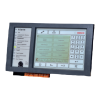
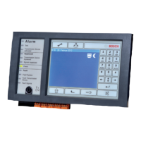
5 Technical Specifications
LCD display / touch screen 320 x 240 pixels / 127.5mmx170mm active surface
Operating and display elements 22 keys, 1 key switch, 12 LEDs, 1 reboot button
Interfaces CAN1, CAN2, ETH1, ETH2, USB, RS232
 Loading...