22 | English
2 609 006 763 | (17.1.13) Bosch Power Tools
Declaration of Conformity
We declare under our sole responsibility that the product de-
scribed under “Technical Data” is in conformity with the fol-
lowing standards or standardization documents: EN 60745
according to the provisions of the directives 2011/65/EU,
2004/108/EC, 2006/42/EC.
Technical file (2006/42/EC) at:
Robert Bosch GmbH, PT/ETM9,
D-70745 Leinfelden-Echterdingen
Robert Bosch GmbH, Power Tools Division
D-70745 Leinfelden-Echterdingen
04.12.2012
Assembly
Mounting the Protective Devices
Before any work on the machine itself, pull the mains
plug.
Note: After breakage of the grinding disc during operation or
damage to the holding fixtures on the protection guard/power
tool, the machine must promptly be sent to an after-sales ser-
vice agent for maintenance for addresses, see section “After-
sales Service and Application Service”.
Protection Guard for Grinding
Place the protection guard 6 onto
the spindle collar of the machine
until the encoding keys of the pro-
tection guard agree with the spin-
dle collar. Press and hold the re-
lease lever 1 while doing this.
Press the protection guard 6 onto
the spindle collar until the shoul-
der of the protection guard is
seated against the flange of the
machine, and turn the protection
guard until it can clearly be heard
to engage.
Adjust the position of the protec-
tion guard 6 to the requirements
of the work process. For this, press the release lever 1 up-
ward and turn the protection guard 6 to the required position.
Always adjust the protection guard 6 in such a manner
that all 3 red cams of release lever 1 engage into the
corresponding notches of the protection guard 6.
Adjust the protection guard 6 in such a manner that
sparking is prevented in the direction of the operator.
The protection guard 6 may be turned only upon actua-
tion of the release lever 1! Otherwise the power tool
may not continue to be used under any circumstances
and must be taken to an after-sales service agent.
Note: The encoding keys on the protection guard 6 ensure
that only a protection guard that fits the machine type can be
mounted.
Protection Guard for Cutting
For cutting with bonded abrasives, always use the pro-
tection guard for cutting 10.
Provide for sufficient dust extraction when cutting
stone.
The protection guard for cutting 10 is mounted in the same
manner as the protection guard for grinding 6.
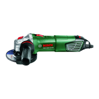
Angle Grinder PWS ... 780-125 7800 850-115 850-125
Article number
3 603 ... CA2 7.. CA2 7.. CA2 7.. CA2 7..
Rated power input
W 780 780 850 850
Rated speed
min
-1
12000 12000 12000 12000
Grinding disc diameter,
max.
mm 125 125 115 125
Thread of grinder spindle
M 14 M 14 M 14 M 14
Thread length (max.) of
grinder spindle
mm 21 21 21 21
Weight according to
EPTA-Procedure
01/2003 with standard-
auxiliary handle
kg 1.8 1.8 1.8 1.8
Protection class
/II /II /II /II
The values given are valid for a nominal voltage [U] of 230 V. For different voltages and models for specific countries, these values can vary.
Dr. Egbert Schneider
Senior Vice President
Engineering
Helmut Heinzelmann
Head of Product Certification
PT/ETM9
OBJ_BUCH-1824-001.book Page 22 Thursday, January 17, 2013 10:33 AM