12/36 Bosch Rexroth AG
Reparaturanleitung/Repair Manual A10VG 28–63
RDE 92750-21-R/02.08
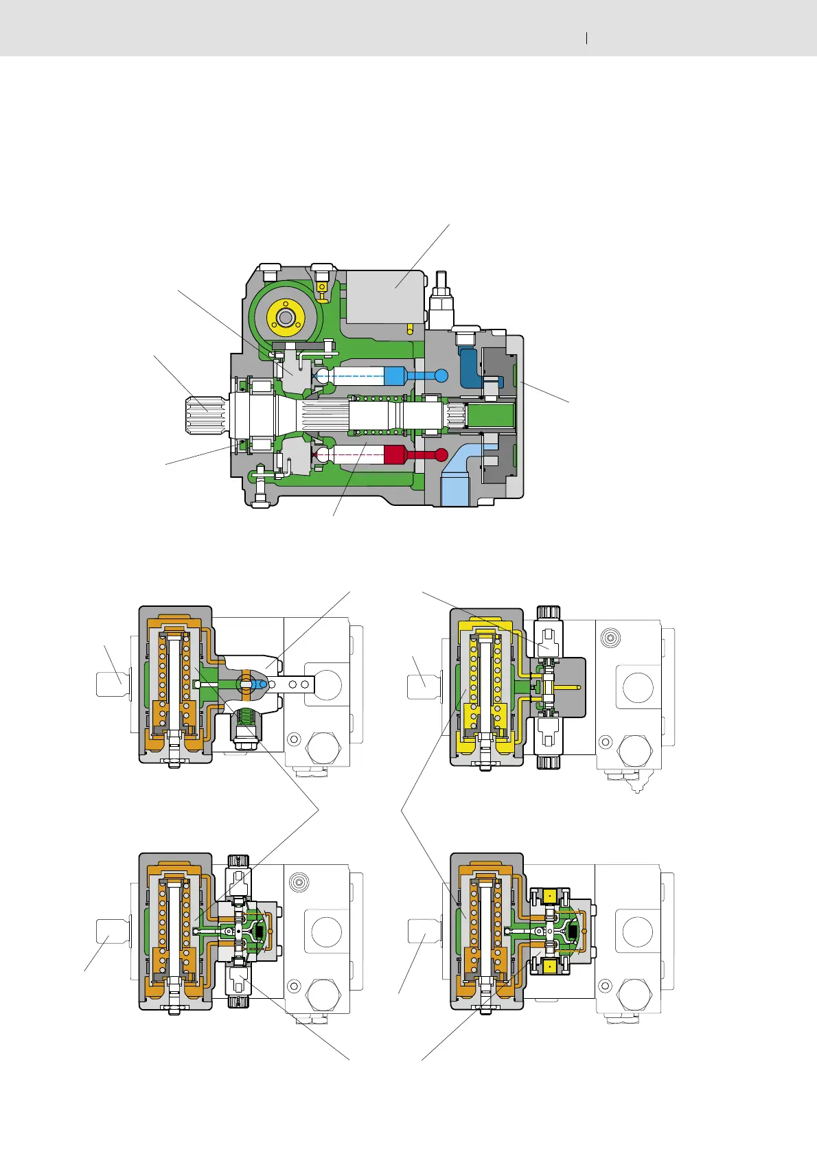
3.2.1 Sectional Drawing
The following drawings show the interrelation of the compon-
ents of the A10VG variable pump.
3.2.1 Schnittzeichnung
Die folgenden Schnittzeichnungen zeigen das Zusammenspiel
der Komponenten der A10VG Verstellpumpe.
Steuergerät
Control unit
Schwenkwiege /
Cradle
Anschlussplatte
mit Hilfspumpe /
Port Plate with
Auxiliary Pump
HWD
Verstellkolben
Control Piston
Antriebswelle /
Drive Shaft
Triebwerk /
Rotary Group
Antriebswelle
Drive Shaft
Steuergerät (siehe unten) /
Control unit (see below)
Seitenansicht / Side View
Draufsicht Verstellungen/
Top View with Controllers
DAD
HDDEPD
Antriebswelle
Drive Shaft
Antriebswelle
Drive Shaft
Antriebswelle
Drive Shaft
Wellendichtring /
Shaft Seal Ring
Steuergerät
Control unit

 Loading...


