Page
5.2.2 Mounting cut-out................................................................................................................................ 22
5.2.3 Mounting Dimensions VDP 16.3........................................................................................................ 23
5.2.4 Mounting dimensions VDP 40.3........................................................................................................ 24
5.2.5 Mounting dimensions VDP 60.3........................................................................................................ 25
5.3 Electric connection................................................................................................................................ 26
5.3.1 Power routing 230 V.......................................................................................................................... 26
5.3.2 Power routing 400 V.......................................................................................................................... 27
5.3.3 Control cabinet PC and display at UPS............................................................................................. 28
5.3.4 Only control cabinet PC connected to UPS....................................................................................... 28
6 Display and operating components.............................................................................. 29
6.1 Backlight switch-off............................................................................................................................... 29
6.2 Operating and error displays................................................................................................................ 29
6.2.1 CDI.................................................................................................................................................... 30
6.2.2 CDI+.................................................................................................................................................. 30
6.2.3 ........................................................................................................................................................... 30
6.3 Foil Keyboard........................................................................................................................................ 30
6.3.1 System requirements......................................................................................................................... 30
6.3.2 Position of the keys........................................................................................................................... 31
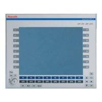
6.3.3 VDP 16.3 Keys and VDP 40.3 Keys.................................................................................................. 31
6.4 Touch screen........................................................................................................................................ 33
7 Interfaces..................................................................................................................... 35
7.1 Interfaces at the VDP............................................................................................................................ 35
7.1.1 Overview............................................................................................................................................ 35
7.1.2 S1 DIP switch.................................................................................................................................... 36
7.1.3 24 V DC voltage supply..................................................................................................................... 37
7.1.4 XUSB Interfaces................................................................................................................................ 38
7.1.5 XSER and XVID interfaces................................................................................................................ 39
7.1.6 XCDI+rx interface.............................................................................................................................. 40
8 Maintenance................................................................................................................ 41
8.1 Maintenance plan................................................................................................................................. 41
8.2 LCD display.......................................................................................................................................... 41
9 IndraControl VDP 16.3/40.3/60.3/90.3/92.3................................................................. 43
9.1 Touch screen........................................................................................................................................ 43
9.2 VDP USB monitor service..................................................................................................................... 43
9.2.1 Function............................................................................................................................................. 43
9.2.2 Installing, uninstalling and exiting the service.................................................................................... 43
10 Environmental protection and disposal ....................................................................... 45
10.1 Environmental protection...................................................................................................................... 45
10.2 Disposal................................................................................................................................................ 45
II
Table of Contents
IndraControl VDP 16.3, VDP 40.3, VDP 60.3 Operator Dis‐
play
Bosch Rexroth AG R911323862_Edition 07
 Loading...