EasyManua.ls Logo

Bosch Rexroth IndraMotion MLD Series User Manual

Bosch Rexroth IndraMotion MLD Series
270 pages
To Next Page IconTo Next Page
Page #1 background imageLoading...
Page #1 background image
The Drive & Control Company
Rexroth IndraDrive
Rexroth IndraMotion MLD (2G)
as of MPx-18
Edition 02
Application Manual
R911338914
LSA Control S.L. www.lsa-control.com comercial@lsa-control.com (+34) 960 62 43 01

Table of Contents

Question and Answer IconNeed help?

Do you have a question about the Bosch Rexroth IndraMotion MLD Series and is the answer not in the manual?

Bosch Rexroth IndraMotion MLD Series Specifications

General IconGeneral
PLC StandardIEC 61131-3
Protection ClassIP20
Power Supply24 VDC
Programming LanguagesInstruction List (IL), Structured Text (ST), Ladder Diagram (LD), Function Block Diagram (FBD), Sequential Function Chart (SFC)
Communication InterfacesPROFIBUS, CANopen
Operating SystemReal-time operating system
MemoryVaries depending on the specific model; typically includes RAM for program execution and Flash memory for program storage
Operating Temperature0°C to 55°C
WeightVaries depending on the specific model

Summary

1.5 Product presentation

1.5.1 Introduction and overview

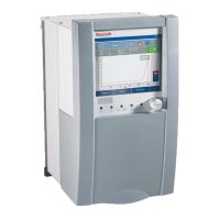
Introduces IndraMotion MLD as an integrated PLC in the Rexroth IndraDrive, combining motion and PLC functions.

1.5.2 Brief description

1.5.3 IndraMotion MLD-S

1.5.4 IndraMotion MLD-M

1.5.5 Digital and analog I/O extensions

1.5.7 Function overview and system properties

General basic functions of the integrated PLC

Discusses freely programmable PLC in accordance with IEC 61131 and programming languages.

Amount of resources (memory)

Performance data

Usage information and applications

Hardware Requirements

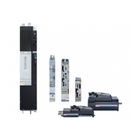
Details the necessary hardware for using the drive-integrated PLC, focusing on power/control sections.

Firmware Requirements

Possible applications of IndraMotion MLD

IndraMotion MLD as intelligent servo axis

Explains how IndraMotion MLD can be used as an intelligent servo axis, managed by a higher-level control unit.

IndraMotion MLD as stand-alone "Motion Logic Control"

Using technology packages and turnkey solutions

2 Important directions for use

2.1 Appropriate use

Details the conditions for appropriate use of Rexroth products, emphasizing safety and proper handling.

2.1.2 Areas of use and application

Describes the intended use of drive controllers for electric motors and monitoring their operation.

2.2 Inappropriate use

3.2 General information

3.2.1 Using the Safety instructions and passing them on to others

Emphasizes reading all documentation before installation and operation, and delivering safety instructions with the component.

3.2.2 Requirements for safe use

Lists instructions for safe use, including observing safety regulations and using only qualified persons.

3.2.3 Hazards by improper use

3.3 Instructions with regard to specific dangers

3.3.1 Protection against contact with electrical parts and housings

Addresses dangers from voltages above 50 volts, emphasizing qualified persons and safe practices.

3.3.2 Protective extra-low voltage as protection against electric shock

3.3.3 Protection against dangerous movements

3.3.4 Protection against electromagnetic and magnetic fields during operation and mounting

3.3.5 Protection against contact with hot parts

3.3.6 Protection during handling and mounting

3.3.7 Battery safety

3.3.8 Protection against pressurized systems

3.4 Explanation of signal words and the Safety alert symbol

4.3 Device control

4.3.3 Axis control

4.3.5 PLC runtime

4.3.6 MLD options for influencing axis control

MLD-M device control

Details the device control of CCD groups in MLD-M, noting additions to MLD-S design.

4.4 Commanding axes

4.4.1 Basics on axis control

Defines axis operating state and primary external control information for commanding the axis.

MLD-S as "intelligent servo axis"

MLD-S as "stand-alone single-axis "Motion Logic Control""

MLD-M as "stand-alone multi-axis "Motion Logic Control""

4.4.2 Implementing motion commanding in the axis

4.4.3 Basic functional principle of motion function blocks in conformity with PLCopen

4.4.4 Axis addressing

General information

Explains that function blocks for motion commanding use axis-related functions, requiring target axis transmission.

Axis availability for functions and function blocks

MLD function blocks and parameters for commanding axes

Parameters and diagnostic messages for commanding axes

Working with retain variables

4.5 Task system

4.5.3 Task properties

4.5.4 Motion task

Motion task in synchronism with CCD

Diagnostics and error messages in relation to a motion task

4.5.5 Task monitoring (watchdog)

4.5.6 Runtime measurements

4.5.8 Task cycle times and timing

4.6 IndraMotion MLD error handling

4.6.1 IndraMotion MLD operating behavior

Describes MLD(-S) and MLD(-M) behavior when programs are modified or downloaded, including axis switching.

4.6.2 General (for MLD-S and MLD-M)

Errors handled in the drive

Details errors handled by the drive firmware, including fatal exception errors and drive warnings.

Errors that can be caused by faulty programming

Lists errors caused by faulty programming, such as array access, division by zero, and watchdog errors.

Errors detected by functions or function blocks

Triggering PLC warnings

Triggering PLC errors

4.6.3 Configuring the error reaction in MLD-S

4.6.4 MLD-M error handling and reaction

Configuring the error reaction for MLD-M

Configuring the MLD-M/CCD error reaction

Describes configuring error reaction for CCD axis groups based on parameter settings (P-0-1800.0.1).

5 MLD communication interfaces and data channels

IndraMotion MLD data channels

5.2 IndraMotion MLD data channels

5.2.1 Cyclic data channels

Provides access to drive internal variables, parameters, and I/O via PLC programs.

I/O Channel (PII, POI)

Memory Ranges and Addressing

"AxisData" cyclic axis data

Configuring user data in "AxisData"

5.2.2 Acyclic data channels / interfaces

Accessing local parameters via direct variables

Parameter channel

Brief description

Explains the parameter channel for acyclic read/write access to S- and P-parameters of the drive.

PLC parameters for general purpose (global registers)

Parameterization and commissioning information

Motion command channel

Activation

Explains activating "Permanent control" of the local axis for MLD motion control.

PLCopen

Operation modes used

"MB_Stop"

"MC_Stop"

"MC_Power"

5.2.3 Configuring the inputs and outputs (I/O configuration of MLD)

Configuring the digital and analog inputs/outputs

Inputs/outputs of the optional module "DA"

Inputs/outputs of remote axes (Slave/Axis2 to 10)

5.2.4 Cyclic data in MLD-M system mode

Process images of the inputs/outputs

6 Visualization and engineering interfaces

Interfaces for connecting operator terminals

Discusses connecting Bosch Rexroth and third-party HMIs to IndraDrive controllers.

Digital and analog inputs/outputs

Hardware requirements

6.2 Interfaces for connecting communication partners

6.2.1 Ethernet interface (TCP/IP)

Explains reaching drive parameters via standard Ethernet interface with TCP/IP protocol.

Setting the IP address

Details setting IP addresses and network masks for connecting devices to a network.

Notes on utilization

6.3 Connecting IndraControl (VCP/VE*)

Requirements

Including the symbol configuration

Symbol configuration for accessing drive parameters

Details including symbol configuration for drive parameters (S- and P-parameters) with VI-Composer.

Symbol configuration for accessing PLC variables of MLD

6.3.3 Notes on utilization for IndraControl VCP

Connecting IndraControl VCP via Ethernet

Provides steps for establishing connection between a drive and IndraControl VCP via Ethernet.

Drive configuration in VI Composer

Configuring IndraControl VCP

Functions of "Setup-Main"

Reading drive parameters

Writing drive parameters

Notes on utilization for IndraControl VE*

Connecting IndraControl VE* via Ethernet

Provides steps for establishing connection between a drive and IndraControl VE* via Ethernet.

7 Notes on commissioning and application

7.1 Requirements for using Rexroth IndraMotion MLD

Outlines firmware, hardware, and software requirements for using Rexroth IndraMotion MLD.

7.1.3 Requirements for communication

7.2 Programming in IndraWorks MLD

7.3 Applications for Rexroth IndraMotion MLD

7.3.2 Using technology functions

Explains technology functions as compiled PLC projects combining IEC or firmware function blocks.

Parameterization and commissioning

7.3.3 Free programming of Rexroth IndraMotion MLD

Connection to the drive

Explains establishing communication between IndraLogic and the drive via IndraWorks MLD commissioning software.

MLD settings in IndraWorks

MLD axis status

Diagnostics for PLC inputs

Diagnostics PLC outputs

Diagnostics PLC registers Ax

Diagnostics PLC registers Gx

Change IndraLogic device version

Configuration

Safe programming

Using pointers

Warns about pointer accesses at runtime and incorrect access causing PLC exceptions.

Stack check

Explains stack requirements checked during compilation to prevent excessive stack usage.

Array access (exceeding the range)

Warns about unchecked array access and potential consequences of index outside the allowed range.

Division by zero

Access to variables via programming system or interface is only byte-consistent

8.5.2 Structuring PLC projects

8.5.3 Programming languages

8.5.4 Global data

8.5.5 Program header

8.5.7 Type identifiers

8.5.9 Definition of standard interfaces in function blocks

8.5.10 Error handling

9.2 Device Editor

9.2.2 Status

9.2.3 Files

9.2.4 Log

9.2.5 PLC Settings

9.3 Diagnostic functions

Oscilloscope function

Explains the oscilloscope function for recording internal/external status variables and its use in commissioning/troubleshooting.

9.3.2 MLD diagnostic functions

Debugging/troubleshooting

Describes the integrated debugger in IndraLogic for setting breakpoints and testing programs.

9.4 Service functions

9.4.1 Service functions of the PLC (IndraMotion MLD)

Lists service functions in IndraWorks (IndraLogic) like Download, Online change, Load boot project, and Clean all.

9.4.2 Changing firmware

Changing the Device Version

Subsequently Installing a Device Version

9.4.4 Replacing the Controller

Overview

Describes controller components (power section, control section) and replacement procedures.

How to Proceed when Replacing Controllers

Replacing Controller and Programming Module

Provides step-by-step instructions for replacing the controller and programming module, including safety warnings.

10 Converting projects

10.1 Introduction

Introduces how to convert IndraLogic 1.x projects (MLD-1G) to IndraLogic 2G projects (MLD-2G).

10.2 Requirements in MLD-1G

Lists requirements in MLD-1G to check/preset for converting projects, including monitoring runtimes.

10.3 Adding to MLD-2G

10.3.1 Adding a project

Details importing existing MLD-1G projects into IndraWorks MLD-2G via the Project Explorer.

10.3.2 Compiling errors after converting projects

Assigning Different Data Types

Calling function blocks or their methods with the function block type

10.3.3 Adjustments in MLD-2G

11 Service and support

Related product manuals