Do you have a question about the Bosch Rexroth NYCe 4000 and is the answer not in the manual?
Details target groups, product phases, and activities related to the document.
Identifies technical and service personnel as the primary readers of this document.
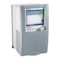
Lists the system housings and instructions included in the delivery.
References other documents containing detailed information.
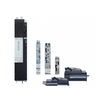
Describes the system housings and their drive module slots.
Lists the items included in the product delivery.
Defines signal words (danger, warning, caution) and alert symbols used.
Lists available accessories like fan units and capacitor kits.
Details operating and storage conditions like temperature and humidity.
Provides power specifications for 24V System, Fast Digital, and Digital inputs.
Lists drive power specifications for system housings.
Details motor connector ratings for NY4120 and NY4140 modules.
Lists applicable standards like IEC 61010-1 and IEC 61000.
Shows the CE logo and references the Declaration of Conformity.
Confirms UL certification for system housings and displays the UL logo.
Provides a table of designations, connection types, and connectors on the base plate and cable.
Explains the 24V SYSTEM connector for power supply to modules.
Mentions capacitor connections for drive slots and safety warnings.
Describes the two types of drive power supply connectors and voltage limits.
Provides instructions for connecting motor cables, emphasizing shielded cables.
Gives guidance on connecting encoder and HALL sensor cables, including shield connections.
Details analog I/O connections, including analog inputs and outputs.
Explains 24V SELV power supply for digital I/O and lists fuse ratings.
Provides general precautions for power off and safe installation.
Lists the mechanical dimensions (width, height, depth) for system housings.
Details minimum ventilation distances and mounting orientations.
Mandates protective earth connection via a threaded post for safety.
Instructs on connecting encoder cable shields and keeping flat band cables short.
Explains how system housing configuration depends on the model and slot types.
Outlines safety precautions and steps for removing the system housing.
Provides instructions for returning products for disposal.
Details product materials and recycling processes for environmental protection.
Provides contact information for the Bosch Rexroth Service department.
Directs users to the website for company addresses and service information.
| Series / Model | NYCe 4000 |
|---|---|
| Manufacturer | Bosch Rexroth |
| Operating Voltage | 24 V DC |
| Protection Class | IP20 |
| PLC functionality | Integrated PLC functionality |
| Communication interfaces | Ethernet/IP, PROFINET |
| Operating Temperature Range | 0 to +50 °C |
| Storage Temperature Range | -25 to +70 °C |
| Weight | Varies depending on the specific module configuration |
| Number of axes | Up to 64 axes |