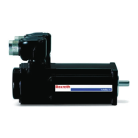
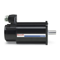
MKE Synchronous Servomotors
Assembly -X2
Pin Signal
1 T1
2 T2
3 BR+
4 BR-
Technical data -X2
Clamping range 2.5 mm
2
Wire stripping length 5.5 mm, use wire end ferrules
Clamping screws (size) M3
Tightening torque clamping
screws
0.5 Nm
Notes about assembly:
•
Insert the plug terminal X2 onto the printed
circuit board and observe correct latch of the
plug-in interlock.
Assembly -X3
Pin Signal [Encoder A, C] Signal [Encoder B, D]
1 ENC_ Encoder ENC_ Encoder
2 n.c. ENC_CLK-.
3 A- A-
4 n.c. ENC_CLK-+
5 A+ A+
6 EncData+ EncData+
7 B- B-
8 EncData- EncData-
9 B+ B+
10 VCC_ Encoder VCC_ Encoder
Technical data -X3
Contact R911260765, Bosch Rexroth
Crimping area 0.32 … 0.52 mm
2
Wire stripping length 3 mm
Crimping tool R911262293, Bosch Rexroth
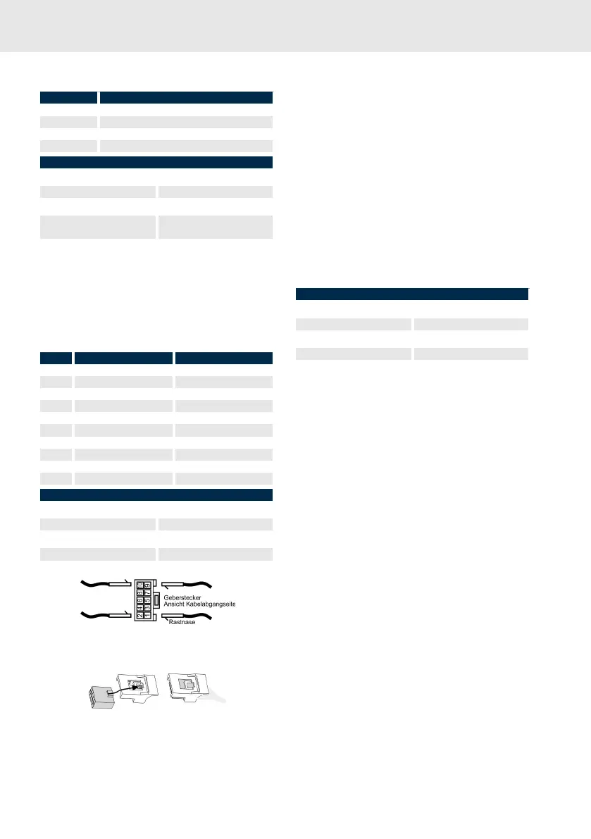
Fig. 11: MKE-X3 Pin assembly
Fig. 12: MKE-X3 Plug-in interlock
Notes about assembly:
• A hand crimping tool to handle the clamp ter-
minal X3 can be ordered at Bosch Rexroth.
Order number: R911262293.
• Assemble the contacts within X3 connector
housing as decribed in the following picture.
•
Assemble the plug-in interlock (0510) on the
connector housing X3.
•
Insert the plug terminal X3 onto the printed
circuit board and observe correct latch of the
plug-in interlock.
Assembly shield connection
Technical data terminal ends
Terminal end M3 R911211410, Bosch Rexroth
Crimping area 0.25 … 1.5 mm
2
Wire stripping length 5 mm
Crimping tool Standard
Tightening torque 1.3 Nm (M3 screw within housing
lid)
Notes about assembly:
•
Use terminal ends to connect the shield con-
nection to the motor housing.
8.3.4
Terminal box (MKE047-E)
electrical connection
The accessory kit SUP-M04-MKE0XX is required
to connect the motors. The accessory kit is
included with the motors at delivery.





 To Next Page