1
M
GYRD-e6-4
GYRD-l5-2
WHVT-e5-1
L1
Drain Motor – m3
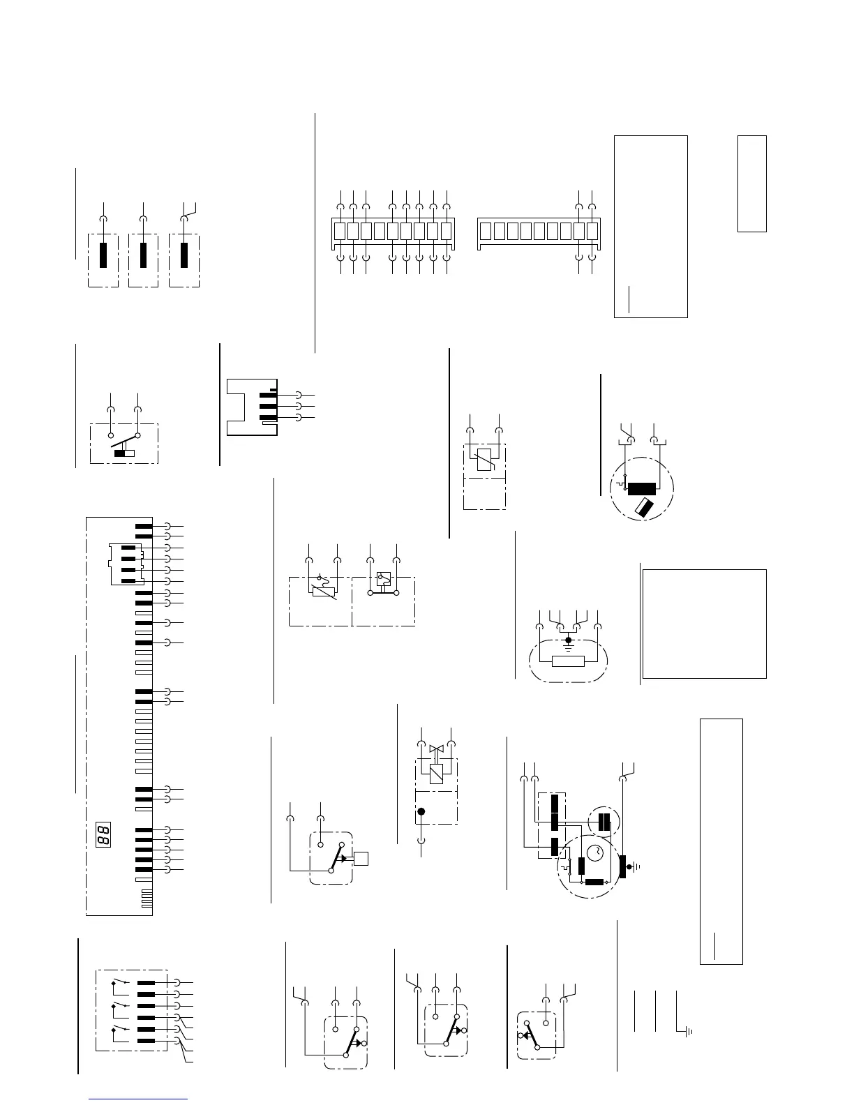
Wire Color Code
BK-a1-4
WH-a1-2
GNYE-r1
L1
N
PE-3
Electrical Supply – l1
RD-e5-4
GNYE-s2
GNYE-m2
GNYE-I1-PE-3
GNYE-PE-2
RD-f5
Heating Element – r1
RD-r1
WHRD-a1-1
WHVT-m3
Flow Switch – e5
4
2
1
BK = black
BN = brown
RD = red
YE = yellow
GN = green
BU = blue
VT = violet
GY = gray
WH = white
PK = pink
HINT: When a wire color consists of four letters,
the 3rd & 4th letters show the stripe. For example,
a “GYBK” wire is a gray wire with a black stripe.
HINT: Format for wire connections
includes wire color and part/terminal
connected to. For example,
“BU-l6-8” = BU (blue wire)
connected to part l6 (rear base
wiring connector) @ terminal 8.
Reed Switch – e3
On/Off Switch – a1
Float Switch – e6
Ground – PE
Actuator (Dispenser) – A2
Circulation Motor– m2
Water Solenoid – s2
Water Level Switch – f1
NTC – f2 & f4 / Thermostat – f5
Aqua Sensor – l4
GNYE-PE-1
J-Box
Control
Hinge
RD-l2.6-1
RD-l2.6-2
GNYE-r1
GNYE-m2
GNYE-PE-4
1
2
4
YE-l2.2-1
YE-l2.2-2
WH-l2.4-2
WH-l2.4-1
BU-f1-4
VT-s2
l6-
9
8
7
6
5
4
3
2
1
RD-f5
GYRD-m3-L1
GN-NTC
BN-l4-3
BN-l4-1
RD-l2.7-3
GYRD-l2.7-2
BU-l2.5-4
GN-NTC BU-l2.5-5
WH-e6-1 WH-l2.2-4
BN-l4-2 BU-l2.5-2
BU-l2.5-3
BU-l2.5-1
l5-
9
8
7
6
5
4
3
2
1
Base Wiring Connectors – I5 & I6
GY-l2.7-1
VT-e1-2
GNYE-PE-1
GNYE-r1
123
K4
GN-l5-5
GN-l5-6
RD-l5-1
RD-r1
f2-f4
f5
185˚F
RD-e6-1
BU-l6-8
P
4
2
1
WH-l5-3
RD-f1-1
GYRD-m3-L1
WH-s2
4
2
1
VT-l6-6
WH-e6-2
GNYE-r1
NTC
N
S
BN-l5-7
3
BN-l5-8
2
BN-l5-9
1
High
Limit
SHU 995x
A2
Control Module– I2
GYRD-l5-2
RD-l5-1
BU-I5-7
BU-I5-8
BU-I5-9
BU-I5-5
BU-I5-6
345261
WH-l6-8
WH-l6-9
345267891
RD-e3
RD-e3
321
3
GY-m2-1
12
GYBK-a1-3
4
I2.x
I2.8-
I2.5- I2.6-
I2.4-
YE-A2
YE-A2
WH-e1-4
WH-l5-3
345267891
WHRD-e1-1
WH-a1-5
21
I2.2-
I2.7-
I2.1-
WHRD-e1
WH-l2.1-1
WHRD-e5-1
WH-l1-N
GYBK-l2.7-4
WH-a1-6
BK-l1-L1
WH-a1-3
21 3456
VT-m2-2
Door Switch – e1
WHRD-a1-1
WHRD-l2.1-2
GY-l2.2-6
4
2
1



 To Next Page